Altera MAX 10 Clocking and PLL User Manual
Page 27
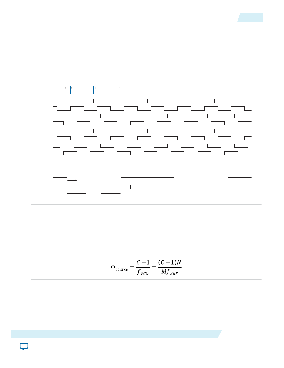
Figure 2-18: Example of Delay Insertion Using VCO Phase Output and Counter Delay Time
The observations in this example are as follows:
•
CLK0
is based on 0° phase from the VCO and has the C value for the counter set to one.
•
CLK1
signal is divided by four, two VCO clocks for high time and two VCO clocks for low time.
CLK1
is
based on the 135° phase tap from the VCO and has the C value for the counter set to one.
•
CLK2
signal is also divided by four. In this case, the two clocks are offset by 3 Φ
fine
.
CLK2
is based on the
0° phase from the VCO but has the C value for the counter set to three. This creates a delay of two
Φ
coarse
(two complete VCO periods).
t
d0-1
t
d0-2
1/8 t
VCO
t
VCO
0
90
135
180
225
270
315
CLK0
CLK1
CLK2
45
Coarse Resolution Phase Shift
Coarse resolution phase shifts are implemented by delaying the start of the counters for a predetermined
number of counter clocks.
Figure 2-19: Coarse Resolution Phase Shift Equation
C in this equation is the count value set for the counter delay time—the initial setting in the PLL usage
section of the compilation report in the Quartus II software. If the initial value is 1, C – 1 = 0° phase shift.
Related Information
•
Dynamic Phase Configuration Implementation
•
Dynamic Phase Configuration Counter Selection
on page 4-16
•
Dynamic Phase Configuration with Advanced Parameters
UG-M10CLKPLL
2015.05.04
Programmable Phase Shift
2-21
MAX 10 Clocking and PLL Architecture and Features
Altera Corporation