Scan chain – Altera MAX 10 Clocking and PLL User Manual
Page 50
cycle, you must set the
rselodd
control bit to 1 to achieve this duty cycle despite an odd division factor.
When you set
rselodd
= 1, subtract 0.5 cycles from the high time and add 0.5 cycles to the low time.
The calculation for the example is shown as follows:
• High time count = 2 cycles
• Low time count = 1 cycle
•
rselodd
= 1 effectively equals:
• High time count = 1.5 cycles
• Low time count = 1.5 cycles
• Duty cycle = (1.5/3)% high time count and (1.5/3)% low time count
Related Information
on page 2-19
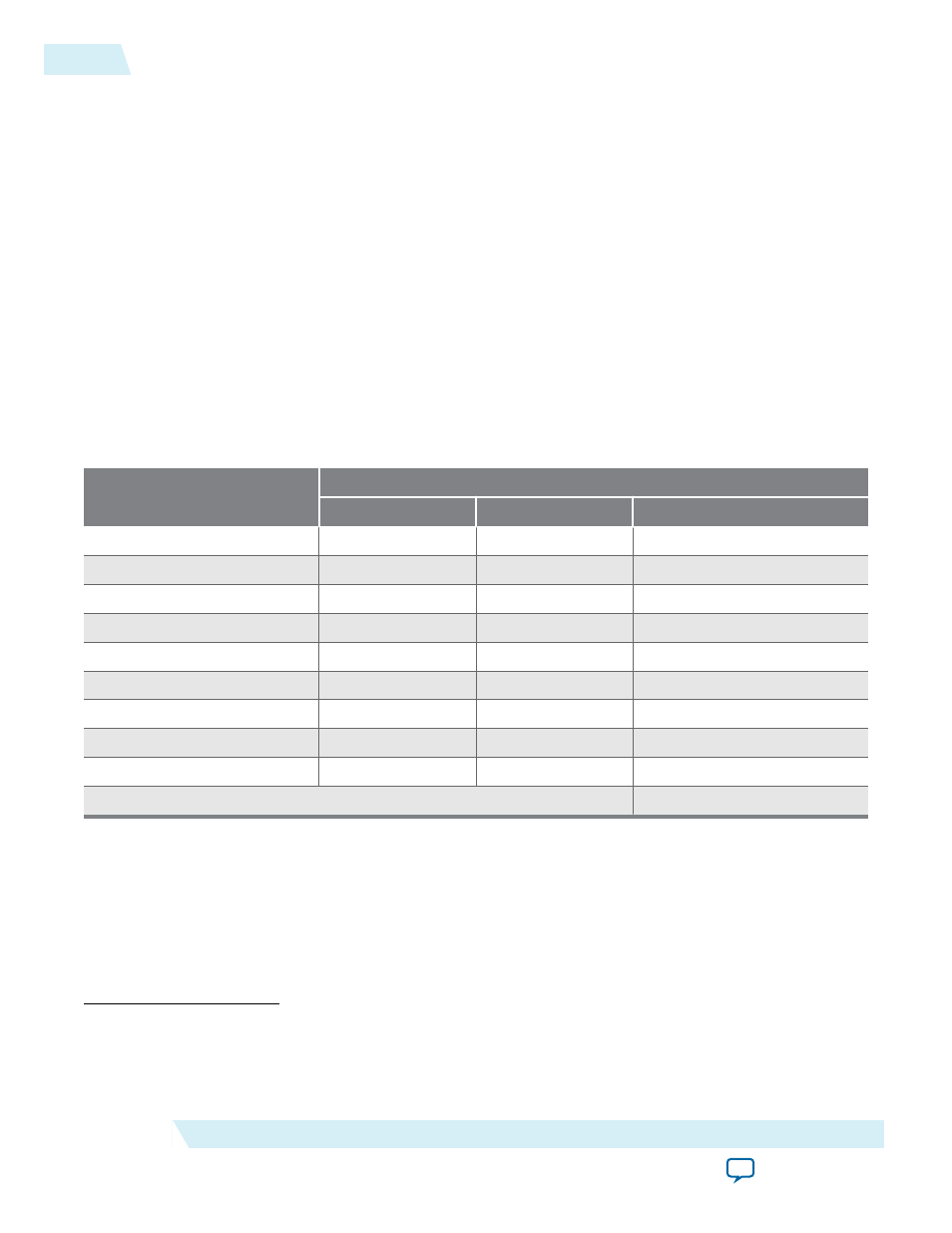
Scan Chain
The MAX 10 PLLs have a 144-bit scan chain.
Table 4-1: PLL Component Reprogramming Bits
Block Name
Number of Bits
Counter
Control Bit
Total
C4
(6)
16
2
(7)
18
C3
16
2
(7)
18
C2
16
2
(7)
18
C1
16
2
(7)
18
C0
16
2
(7)
18
M
16
2
(7)
18
N
16
2
(7)
18
Charge Pump
9
0
9
Loop Filter
(8)
9
0
9
Total number of bits
144
(6)
LSB bit for
C4
low-count value is the first bit shifted into the scan chain.
(7)
These two control bits include
rbypass
, for bypassing the counter, and
rselodd
, for selecting the output
clock duty cycle.
(8)
MSB bit for loop filter is the last bit shifted into the scan chain.
4-12
Scan Chain
UG-M10CLKPLL
2015.05.04
Altera Corporation
MAX 10 Clocking and PLL Implementation Guides