Dynamic phase configuration counter selection – Altera MAX 10 Clocking and PLL User Manual
Page 54
•
on page 7-1
Provides more information about the ALTPLL_RECONFIG IP core parameter settings in the Quartus
II software.
•
PLL Dynamic Reconfiguration Parameter Settings
Provides more information about the ALTPLL IP core parameter settings in the Quartus II software.
•
on page 7-1
Provides more information about the ALTPLL_RECONFIG IP core parameter settings in the Quartus
II software.
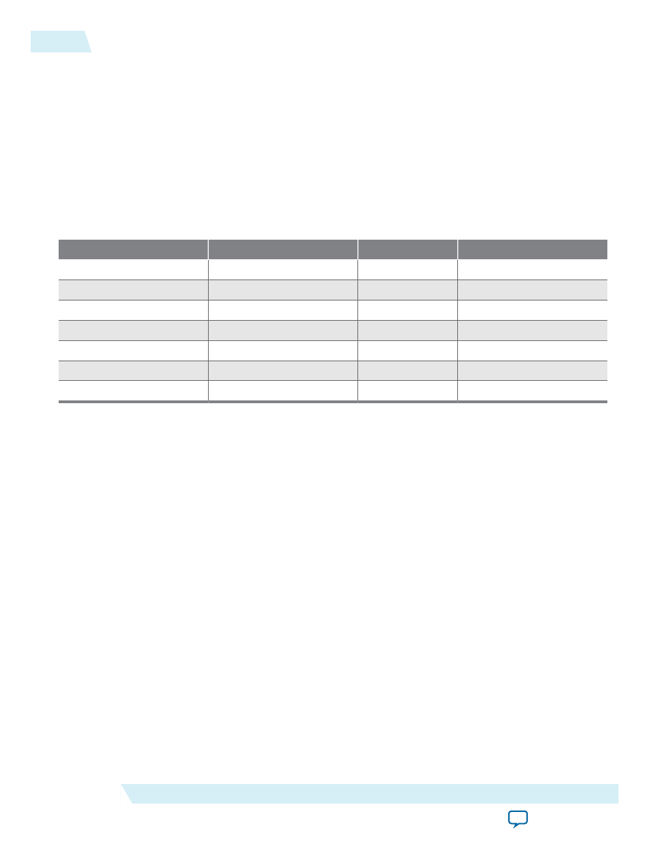
Dynamic Phase Configuration Counter Selection
Table 4-6: Phase Counter Select Mapping
PLL Counter Selection
PHASECOUNTERSELECT [2]
[1]
[0]
All output counters
0
0
0
M
counter
0
0
1
C0
counter
0
1
0
C1
counter
0
1
1
C2
counter
1
0
0
C3
counter
1
0
1
C4
counter
1
1
0
Related Information
Dynamic Phase Configuration with Advanced Parameters
The finest phase shift step resolution you can get in the ALTPLL IP core is 1/8 of the VCO period. If the
VCO frequency is at the lower end of the supported VCO range, the phase shift step resolution might be
larger than preferred for your design.
You can modify your phase shift resolution using the dynamic phase reconfiguration feature of the PLL. If
you want to modify the phase shift resolution without the dynamic phase reconfiguration feature enabled,
perform the following steps:
1. Create an ALTPLL instance. Make sure you specify the speed grade of your target device and the PLL
type.
2. On the PLL Reconfiguration page, turn on Create optional inputs for dynamic phase reconfigura‐
tion and Enable phase shift step resolution.
3. On the Output Clocks page, set your desired phase shift for each required output clock. Note all the
internal PLL settings shown.
4. On the Bandwidth/SS page, click More Details to see the internal PLL settings. Note all of the settings
shown.
5. On the Inputs/Lock page, turn on Create output file(s) using the ‘Advanced’ PLL Parameters.
6. Return to the PLL Reconfiguration page and turn off Create Optional Inputs for Dynamic Phase
Reconfiguration.
7. Click Finish to generate the PLL instantiation file(s).
4-16
Dynamic Phase Configuration Counter Selection
UG-M10CLKPLL
2015.05.04
Altera Corporation
MAX 10 Clocking and PLL Implementation Guides