Altera MAX 10 Clocking and PLL User Manual
Page 33
The following PLL components are configurable in real time:
• Pre-scale counter (
N
)
• Feedback counter (
M
)
• Post-scale output counters (
C0
-
C4
)
• Charge pump current (I
CP
)
• Loop filter components (R, C)
You can use these PLL components to update the following settings in real time without reconfiguring the
entire FPGA:
• Output clock frequency
• PLL bandwidth
• Phase shift
The ability to reconfigure the PLL in real time is useful in applications that may operate in multiple
frequencies. It is also useful in prototyping environments, allowing you to sweep PLL output frequencies
and dynamically adjust the output clock phase.
For instance, a system generating test patterns is required to generate and send patterns at 75 or 150 MHz,
depending on the requirements of the device under test. Reconfiguring the PLL components in real time
allows you to switch between two such output frequencies in a few microseconds.
You can also use this feature to adjust clock-to-out (t
CO
) delays in real time by changing the PLL output
clock phase shift. This approach eliminates the need to regenerate a configuration file with the new PLL
settings.
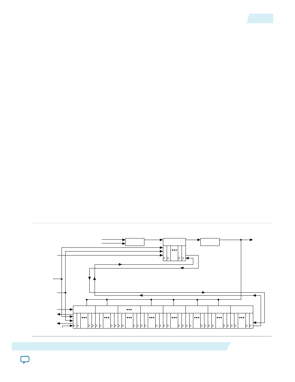
Figure 2-24: PLL Reconfiguration Scan Chain
This figure shows the dynamic adjustment of the PLL counter settings by shifting their new settings into a
serial shift register chain or scan chain. Serial data shifts to the scan chain via the
scandata
port, and shift
registers are clocked by
scanclk
. The maximum
scanclk
frequency is 100 MHz. After shifting the last bit
of data, asserting the
configupdate
signal for at least one
scanclk
clock cycle synchronously updates the
PLL configuration bits with the data in the scan registers.
/C4
/C3
/C2
/C1
/C0
/M
/N
scanclk
scandone
scandata
LF/K/CP
configupdate
inclk
PFD
VCO
FVCO
scanclkena
scandataout
from M counter
from N counter
UG-M10CLKPLL
2015.05.04
PLL Reconfiguration
2-27
MAX 10 Clocking and PLL Architecture and Features
Altera Corporation