Manual clock switchover – Altera MAX 10 Clocking and PLL User Manual
Page 31
You must choose the backup clock frequency and set the
M
,
N
, and
C
counters so that the VCO operates
within the recommended frequency range.
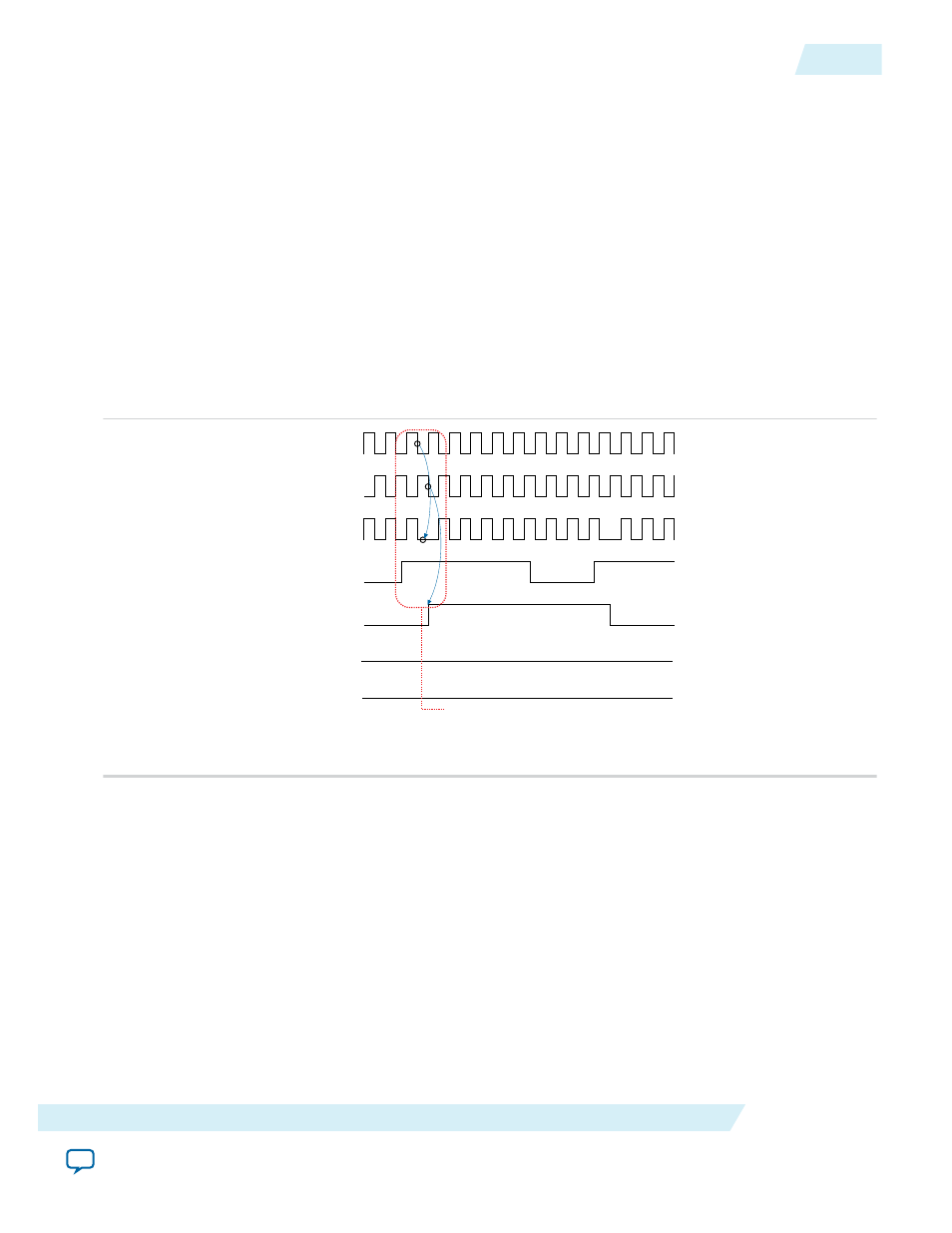
The following figure shows a clock switchover waveform controlled by the
clkswitch
signal. In this case,
both clock sources are functional and
inclk0
is selected as the reference clock. The
clkswitch
signal goes
high, which starts the switchover sequence. On the falling edge of
inclk0
, the counter’s reference clock,
muxout
, is gated off to prevent clock glitching. On the falling edge of
inclk1
, the reference clock
multiplexer switches from
inclk0
to
inclk1
as the PLL reference. The
activeclock
signal is asserted to
indicate the clock that is currently feeding the PLL, which is
inclk1
.
In automatic override with manual switchover mode, the
activeclock
signal mirrors the
clkswitch
signal. Since both clocks are still functional during the manual switch, neither
clkbad
signal goes high.
Because the switchover circuit is positive-edge sensitive, the falling edge of the
clkswitch
signal does not
cause the circuit to switch back from
inclk1
to
inclk0
. When the
clkswitch
signal goes high again, the
process repeats.
Figure 2-22: Example of Clock Switchover Using the
clkswitch
(Manual) Control
inclk0
inclk1
muxout
clkswitch
activeclock
clkbad0
clkbad1
To initiate a manual clock switchover event,
both inclk0 and inclk1 must be running when
the clkswitch signal goes high.
The
clkswitch
signal and automatic switch work only if the clock being switched to is available. If the
clock is not available, the state machine waits until the clock is available.
Manual Clock Switchover
In manual clock switchover mode, the
clkswitch
signal controls whether
inclk0
or
inclk1
is selected as
the input clock to the PLL. By default,
inclk0
is selected.
A clock switchover event is initiated when the
clkswitch
signal transitions from logic low to logic high,
and is being held high for at least three
inclk
cycles. You must bring the
clkswitch
signal back to low
again to perform another switchover event. If you do not require another switchover event, you can leave
the
clkswitch
signal in a logic high state after the initial switch. Pulsing the
clkswitch
signal high for at
least three
inclk
cycles performs another switchover event.
UG-M10CLKPLL
2015.05.04
Manual Clock Switchover
2-25
MAX 10 Clocking and PLL Architecture and Features
Altera Corporation