Pll control signals, Pll control signals -13 – Altera MAX 10 Clocking and PLL User Manual
Page 19
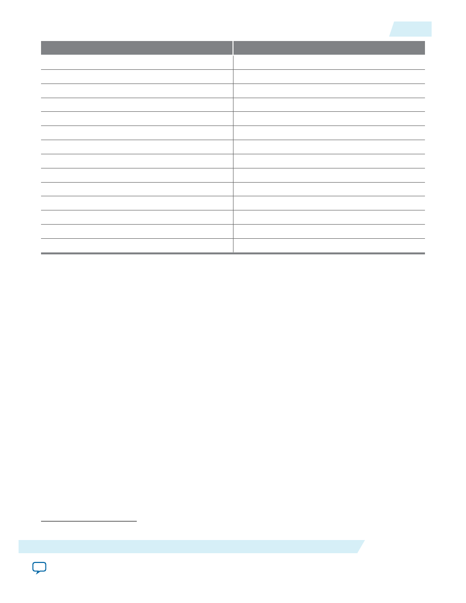
PLL Counter Output
GCLK
PLL2_C1
GCLK[6,9,11,14]
PLL2_C2
GCLK[5,7,10,12]
PLL2_C3
GCLK[6,8,11,13]
PLL2_C4
GCLK[7,9,12,14]
PLL3_C0
(5)
GCLK[0,3,10,13]
PLL3_C1
(5)
GCLK[1,4,11,14]
PLL3_C2
(5)
GCLK[0,2,10,12]
PLL3_C3
(5)
GCLK[1,3,11,13]
PLL3_C4
(5)
GCLK[2,4,12,14]
PLL4_C0
(5)
GCLK[5,8,15,18]
PLL4_C1
(5)
GCLK[6,9,16,19]
PLL4_C2
(5)
GCLK[5,7,15,17]
PLL4_C3
(5)
GCLK[6,8,16,18]
PLL4_C4
(5)
GCLK[7,9,17,19]
PLL Control Signals
You can use the following three signals to observe and control the PLL operation and resynchronization.
pfdena
Use the
pfdena
signal to maintain the last locked frequency so that your system has time to store its
current settings before shutting down.
The
pfdena
signal controls the PFD output with a programmable gate. The PFD circuit is enabled by
default. When the PFD circuit is disabled, the PLL output does not depend on the input clock, and tends
to drift outside of the lock window.
areset
The
areset
signal is the reset or resynchronization input for each PLL. The device input pins or internal
logic can drive these input signals.
When you assert the
areset
signal, the PLL counters reset, clearing the PLL output and placing the PLL
out of lock. The VCO is then set back to its nominal setting. When the
areset
signal is deasserted, the
PLL resynchronizes to its input as it relocks.
The assertion of the
areset
signal does not disable the VCO, but instead resets the VCO to its nominal
value. The only time that the VCO is completely disabled is when you do not have a PLL instantiated in
your design.
(5)
This only applies to 10M16, 10M25, 10M40, and 10M50 devices.
UG-M10CLKPLL
2015.05.04
PLL Control Signals
2-13
MAX 10 Clocking and PLL Architecture and Features
Altera Corporation