Expanding the pll lock range – Altera MAX 10 Clocking and PLL User Manual
Page 46
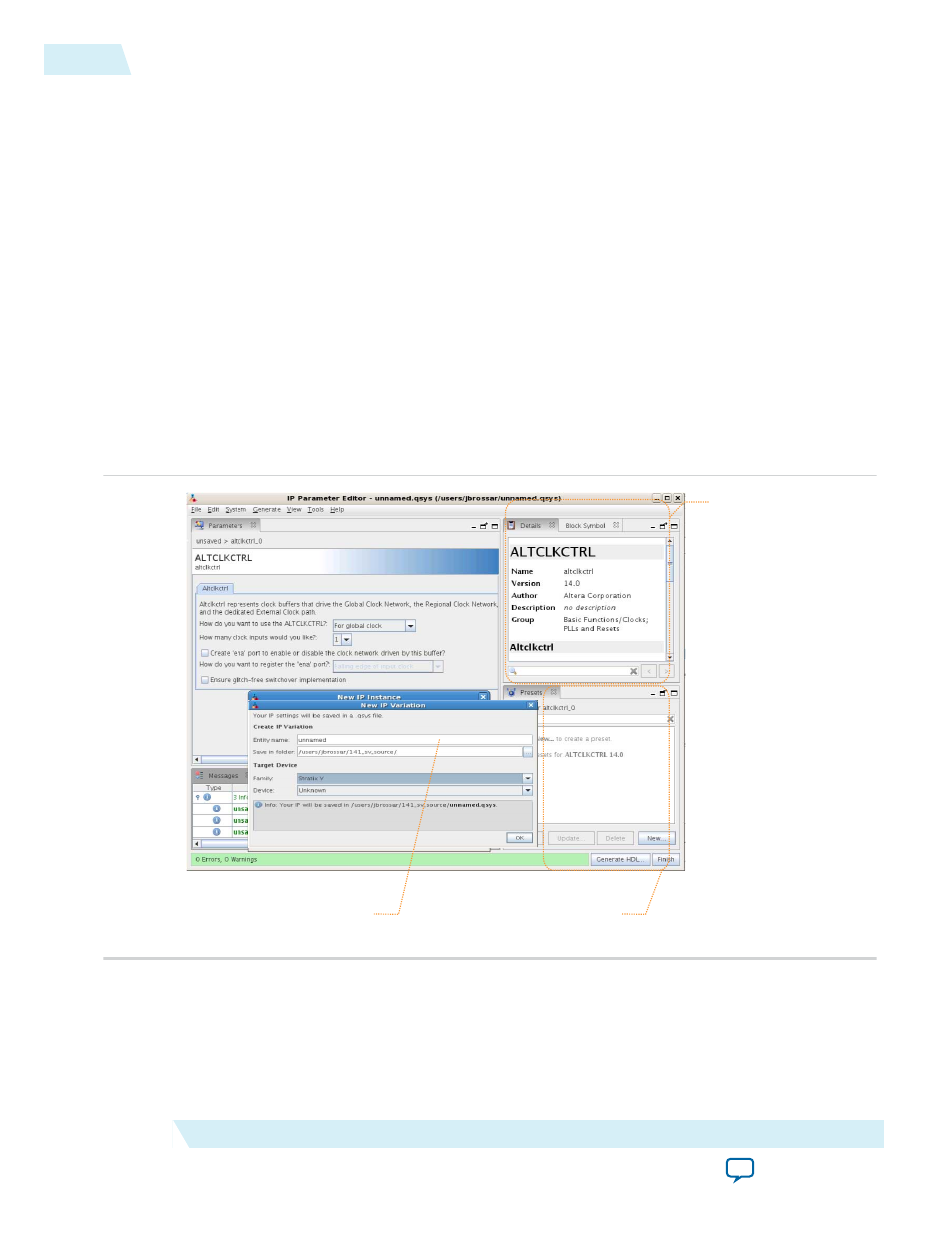
• Optionally select preset parameter values if provided for your IP core. Presets specify initial
parameter values for specific applications.
• Specify parameters defining the IP core functionality, port configurations, and device-specific
features.
• Specify options for processing the IP core files in other EDA tools.
4. Click Generate HDL, the Generation dialog box appears.
5. Specify output file generation options, and then click Generate. The IP variation files generate
according to your specifications.
6. To generate a simulation testbench, click Generate > Generate Testbench System.
7. To generate an HDL instantiation template that you can copy and paste into your text editor, click
Generate > HDL Example.
8. Click Finish. The parameter editor adds the top-level
.qsys
file to the current project automatically. If
you are prompted to manually add the
.qsys
file to the project, click Project > Add/Remove Files in
Project to add the file.
9. After generating and instantiating your IP variation, make appropriate pin assignments to connect
ports.
Figure 4-5: IP Parameter Editor
View IP port
and parameter
details
Apply preset parameters for
specific applications
Specify your IP variation name
and target device
Expanding the PLL Lock Range
The PLL lock range is between the minimum (Freq min lock parameter) and maximum (Freq min lock
parameter) input frequency values for which the PLL can achieve lock. Changing the input frequency
might cause the PLL to lose lock, but if the input clock remains within the minimum and maximum
frequency specifications, the PLL is able to achieve lock. The Quartus II software shows these input
4-8
Expanding the PLL Lock Range
UG-M10CLKPLL
2015.05.04
Altera Corporation
MAX 10 Clocking and PLL Implementation Guides