Clock enable signals, Clock enable signals -7 – Altera MAX 10 Clocking and PLL User Manual
Page 13
Related Information
•
on page 5-1
•
on page 5-2
Clock Enable Signals
The MAX 10 devices support
clkena
signals at the GCLK network level. This allows you to gate off the
clock even when a PLL is used. After reenabling the output clock, the PLL does not need a resynchroniza‐
tion or relock period because the circuit gates off the clock at the clock network level. In addition, the PLL
can remain locked independent of the
clkena
signals because the loop-related counters are not affected.
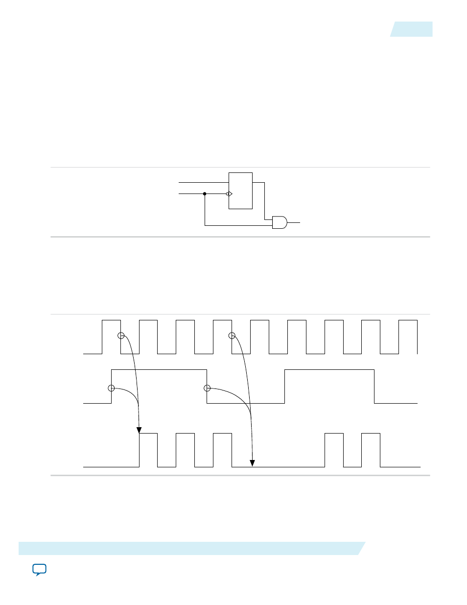
Figure 2-5: clkena Implementation
clkena
clkena_out
clk_out
clkin
D
Q
Note: The
clkena
circuitry controlling the
C0
output of the PLL to an output pin is implemented with
two registers instead of a single register.
Figure 2-6: Example Waveform of clkena Implementation with Output Enable
The
clkena
signal is sampled on the falling edge of the clock (
clkin
). This feature is useful for
applications that require low power or sleep mode.
clkin
clkena
clk_out
The
clkena
signal can also disable clock outputs if the system is not tolerant to frequency overshoot
during PLL resynchronization.
UG-M10CLKPLL
2015.05.04
Clock Enable Signals
2-7
MAX 10 Clocking and PLL Architecture and Features
Altera Corporation