Post-scale counters (c0 to c4) – Altera MAX 10 Clocking and PLL User Manual
Page 49
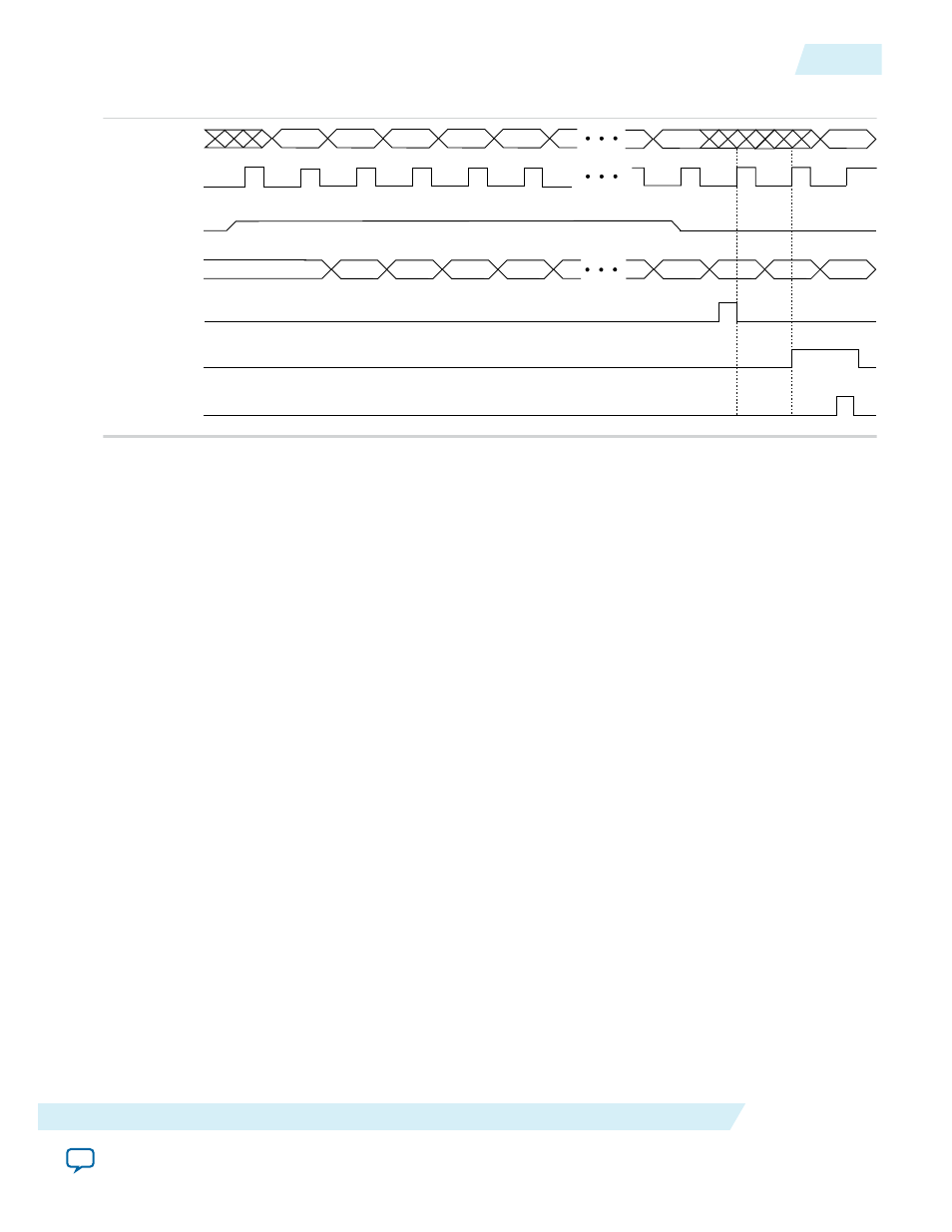
Figure 4-6: PLL Reconfiguration Scan Chain Functional Simulation
scandata
scanclk
scanclkena
scandataout
configupdate
scandone
areset
Dn_old
D0_old
Dn
D0
Dn
LSB
When reconfiguring the counter clock frequency, you cannot reconfigure the corresponding counter
phase shift settings using the same interface. You can reconfigure phase shifts in real time using the
dynamic phase shift reconfiguration interface. If you wish to keep the same nonzero phase shift setting
(for example, 90°) on the clock output, you must reconfigure the phase shift after reconfiguring the
counter clock frequency.
Related Information
on page 2-26
Post-Scale Counters (C0 to C4)
You can configure the multiply or divide values and duty cycle of the post-scale counters in real time.
Each counter has an 8-bit high time setting and an 8-bit low time setting. The duty cycle is the ratio of
output high or low time to the total cycle time, which is the sum of the two.
The post-scale counters have two control bits:
•
rbypass
—For bypassing the counter
•
rselodd
—For selecting the output clock duty cycle
When the
rbypass
bit is set to 1, it bypasses the counter, resulting in a division by one. When this bit is
set to 0, the PLL computes the effective division of the VCO output frequency based on the high and low
time counters. The PLL implements this duty cycle by transitioning the output clock from high-to-low on
the rising edge of the VCO output clock.
For example, if the post-scale divide factor is 10, the high and low count values are set to 5 and 5
respectively, to achieve a 50–50% duty cycle. However, a 4 and 6 setting for the high and low count values,
respectively, would produce an output clock with 40–60% duty cycle.
The
rselodd
bit indicates an odd divide factor for the VCO output frequency with a 50% duty cycle. The
PLL implements this duty cycle by transitioning the output clock from high-to-low on a falling edge of the
VCO output clock.
For example, if the post-scale divide factor is 3, the high and low time count values are 2 and 1
respectively, to achieve this division. This implies a 67%–33% duty cycle. If you need a 50%–50% duty
UG-M10CLKPLL
2015.05.04
Post-Scale Counters (C0 to C4)
4-11
MAX 10 Clocking and PLL Implementation Guides
Altera Corporation