Guideline: .mif streaming in pll reconfiguration, Guideline: scandone signal for pll reconfiguration – Altera MAX 10 Clocking and PLL User Manual
Page 38
• The phase relationship between the input clock to the PLL and output clock from the PLL is important
in your design. Assert
areset
for 10 ns after performing a clock switchover. Wait for the locked signal
(or gated lock) to go high before reenabling the output clocks from the PLL.
• Disable the system during switchover if the system is not tolerant of frequency variations during the
PLL resynchronization period. You can use the
clkbad[0]
and
clkbad[1]
status signals to turn off the
PFD (
pfdena
= 0) so that the VCO maintains its last frequency. You can also use the switchover state
machine to switch over to the secondary clock. After enabling the PFD, the output clock enable signals
(
clkena
) can disable clock outputs during the switchover and resynchronization period. After the lock
indication is stable, the system can reenable the output clock or clocks.
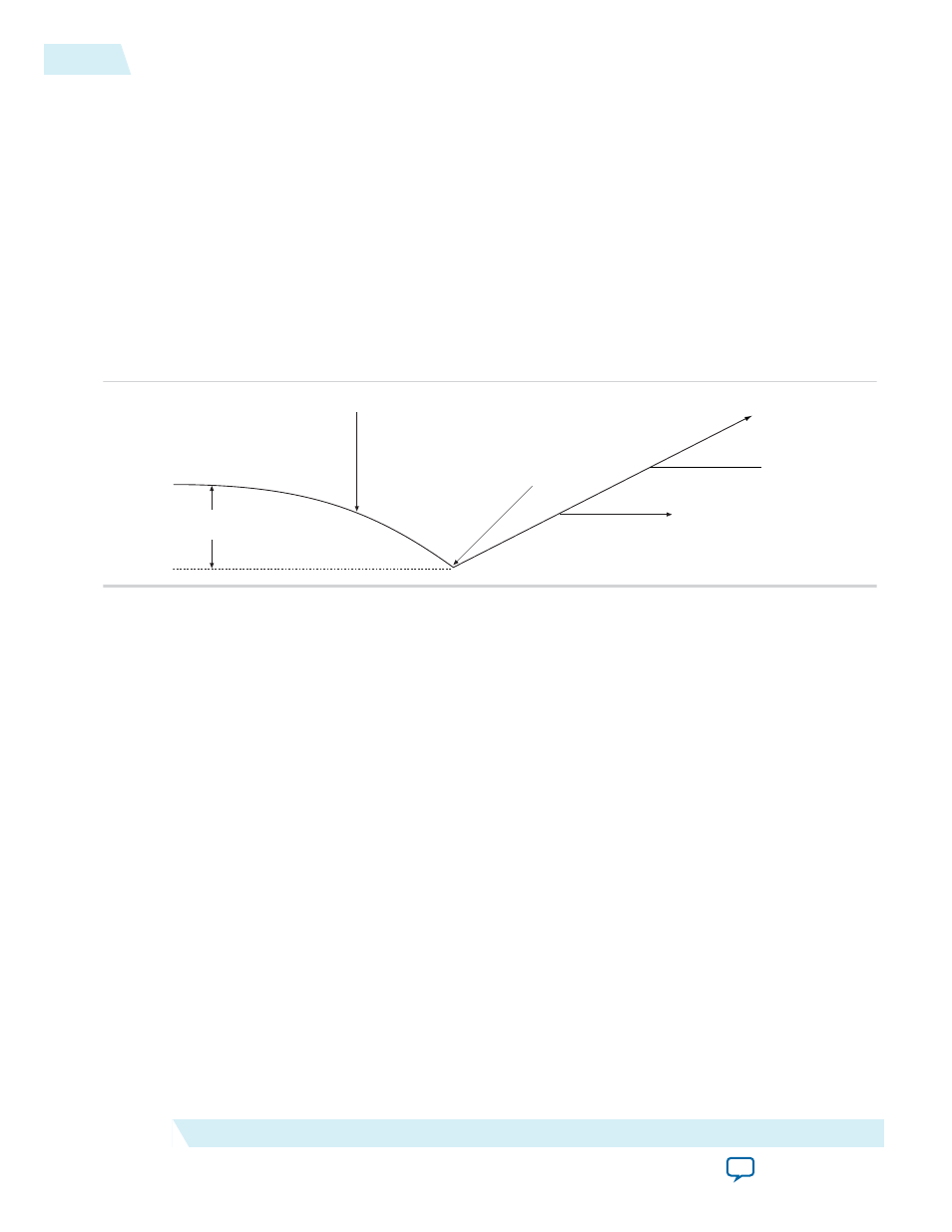
• The VCO frequency gradually decreases when the primary clock is lost and then increases as the VCO
locks onto the secondary clock, as shown in the following figure. After the VCO locks onto the
secondary clock, some overshoot can occur (an over-frequency condition) in the VCO frequency.
Figure 3-1: VCO Switchover Operating Frequency
ΔFvco
Primary Clock Stops Running
Switchover Occurs
VCO Tracks Secondary Clock
Frequency Overshoot
Related Information
•
•
Clock Switchover Parameter Settings
on page 6-3
Guideline: .mif Streaming in PLL Reconfiguration
Consider the following guidelines when using
.mif
streaming in PLL reconfiguration:
• 10M02 devices do not support
.mif
streaming in PLL reconfiguration due to flash size limitation. Altera
recommends using an external flash.
• 10M04, 10M08, 10M16, 10M25, 10M40, and 10M50 devices only support
.mif
streaming in single
image mode. Altera recommends using an external flash for dual image mode. The MAX 10 devices do
not support using both dual image mode and PLL reconfiguration with
.mif
simultaneously.
Related Information
on page 2-26
Guideline: scandone Signal for PLL Reconfiguration
scandone
signal must be low before the second PLL reconfiguration. For
scandone
signal to go low, PLL
areset
signal must be asserted.
3-4
Guideline: .mif Streaming in PLL Reconfiguration
UG-M10CLKPLL
2015.05.04
Altera Corporation
MAX 10 Clocking and PLL Design Considerations