Clock feedback modes, Clock feedback modes -14 – Altera MAX 10 Clocking and PLL User Manual
Page 20
locked
The
locked
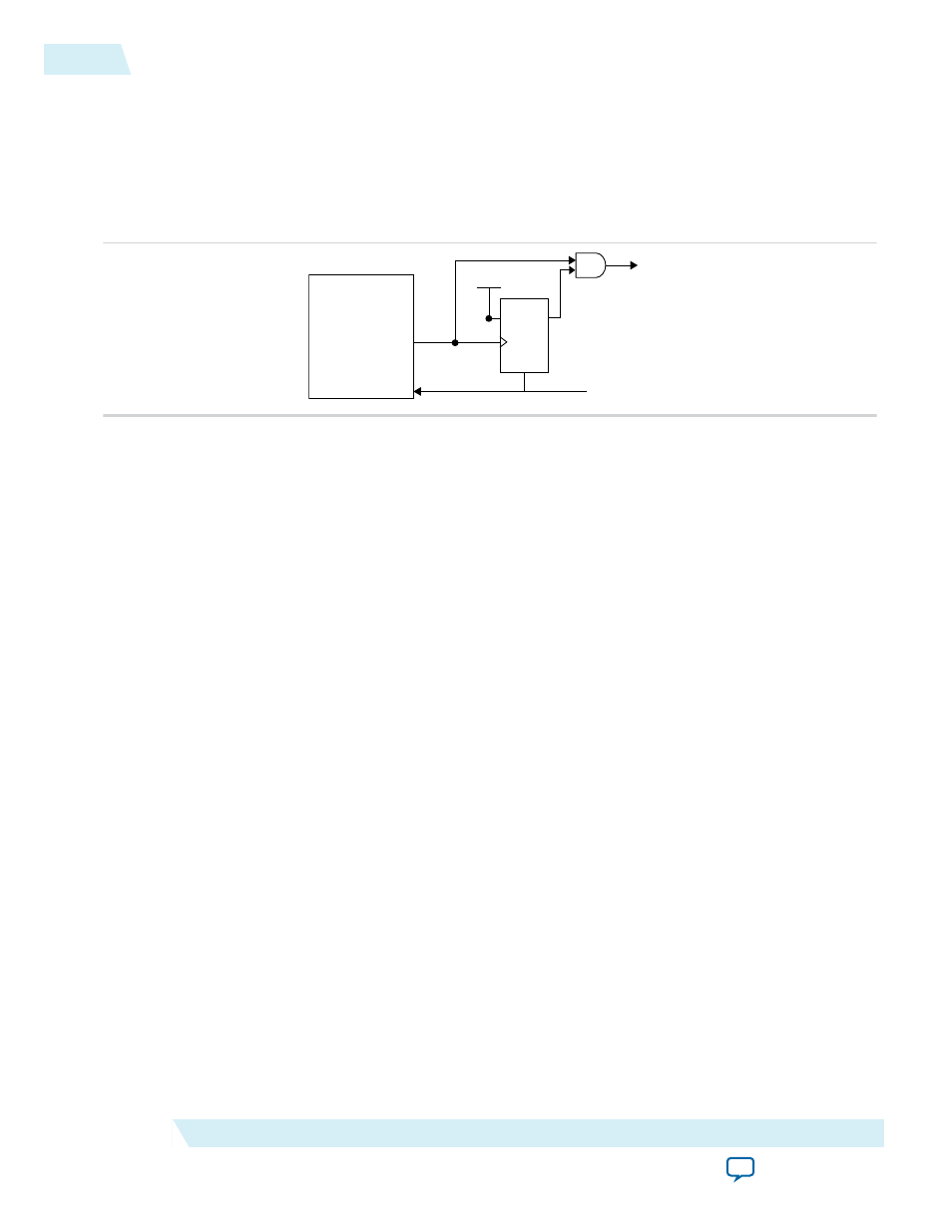
output indicates that the PLL has locked onto the reference clock and the PLL clock outputs
are operating at the desired phase and frequency set in the ALTPLL IP core parameter editor.
Altera recommends using the
areset
and
locked
signals in your designs to control and observe the status
of your PLL. This implementation is illustrated in the following figure.
Figure 2-11: locked Signal Implementation
DFF
D
Q
PLL
locked
locked
areset
VCC
Note: If you use the SignalTap
®
II tool to probe the
locked
signal before the D flip-flop, the
locked
signal goes low only when
areset
is deasserted. If the
areset
signal is not enabled, the extra logic
is not implemented in the ALTPLL IP core.
Related Information
•
Guideline: PLL Control Signals
•
PLL Control Signals Parameter Settings
on page 6-2
•
on page 6-6
Clock Feedback Modes
The MAX 10 PLLs support up to four different clock feedback modes. Each mode allows clock multiplica‐
tion and division, phase shifting, and programmable duty cycle.
The PLL fully compensates input and output delays only when you use the dedicated clock input pins
associated with a given PLL as the clock sources.
For example, when using
PLL1
in normal mode, the clock delays from one of the following clock input
pins to the PLL and the PLL clock output-to-destination register are fully compensated:
•
CLK0
•
CLK1
•
CLK2
•
CLK3
When driving the PLL using the GCLK network, the input and output delays might not be fully
compensated in the Quartus II software.
Related Information
Operation Modes Parameter Settings
2-14
Clock Feedback Modes
UG-M10CLKPLL
2015.05.04
Altera Corporation
MAX 10 Clocking and PLL Architecture and Features