Altera MAX 10 Clocking and PLL User Manual
Page 55
When using Advanced Parameters, the PLL wrapper file (<ALTPLL_instantiation_name>
.v
or
<ALTPLL_instantiation_name>
.vhd
) is written in a format that allows you to identify the PLL
parameters. The parameters are listed in the Generic Map section of the VHDL file, or in the
defparam
section of the Verilog file.
8. Open your PLL instantiation wrapper file and locate either the Generic Map or the
defparam
section.
9. Modify the settings to match the settings that you noted in steps 3 and 4.
10.Save the PLL instantiation wrapper file and compile your design.
11.Verify that the output clock frequencies and phases are correct in the PLL Usage report located under
the Resource section of the Fitter folder in the Compilation Report.
By using this technique, you can apply valid PLL parameters as provided by the ALTPLL IP core
parameter editor to optimize the settings for your design.
Alternatively, you can leave the dynamic phase reconfiguration option enabled and tie the relevant input
ports—
phasecounterselect[3..0]
,
phaseupdown
,
phasestep
, and
scanclk
—to constants, if you prefer
not to manually edit the PLL wrapper file using the Advanced PLL Parameters option.
Related Information
Files Generated for Altera IP Cores (Legacy Parameter Editor)
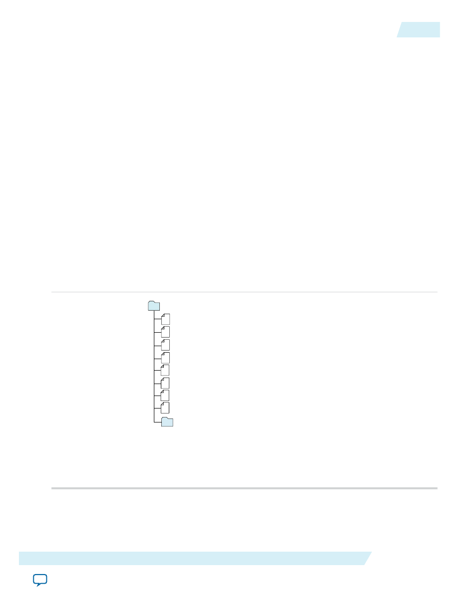
The Quartus II generates the following output for IP cores that use the legacy MegaWizard parameter
editor.
Figure 4-10: IP Core Generated Files
Notes:
1. If supported and enabled for your IP variation
2. If functional simulation models are generated
3. Ignore this directory
<your_ip>.v or .vhd - Top-level IP synthesis file
greybox_tmp
3
UG-M10CLKPLL
2015.05.04
Files Generated for Altera IP Cores (Legacy Parameter Editor)
4-17
MAX 10 Clocking and PLL Implementation Guides
Altera Corporation