Ds4830a user’s guide – Maxim Integrated DS4830A Optical Microcontroller User Manual
Page 78
DS4830A User’s Guide
78
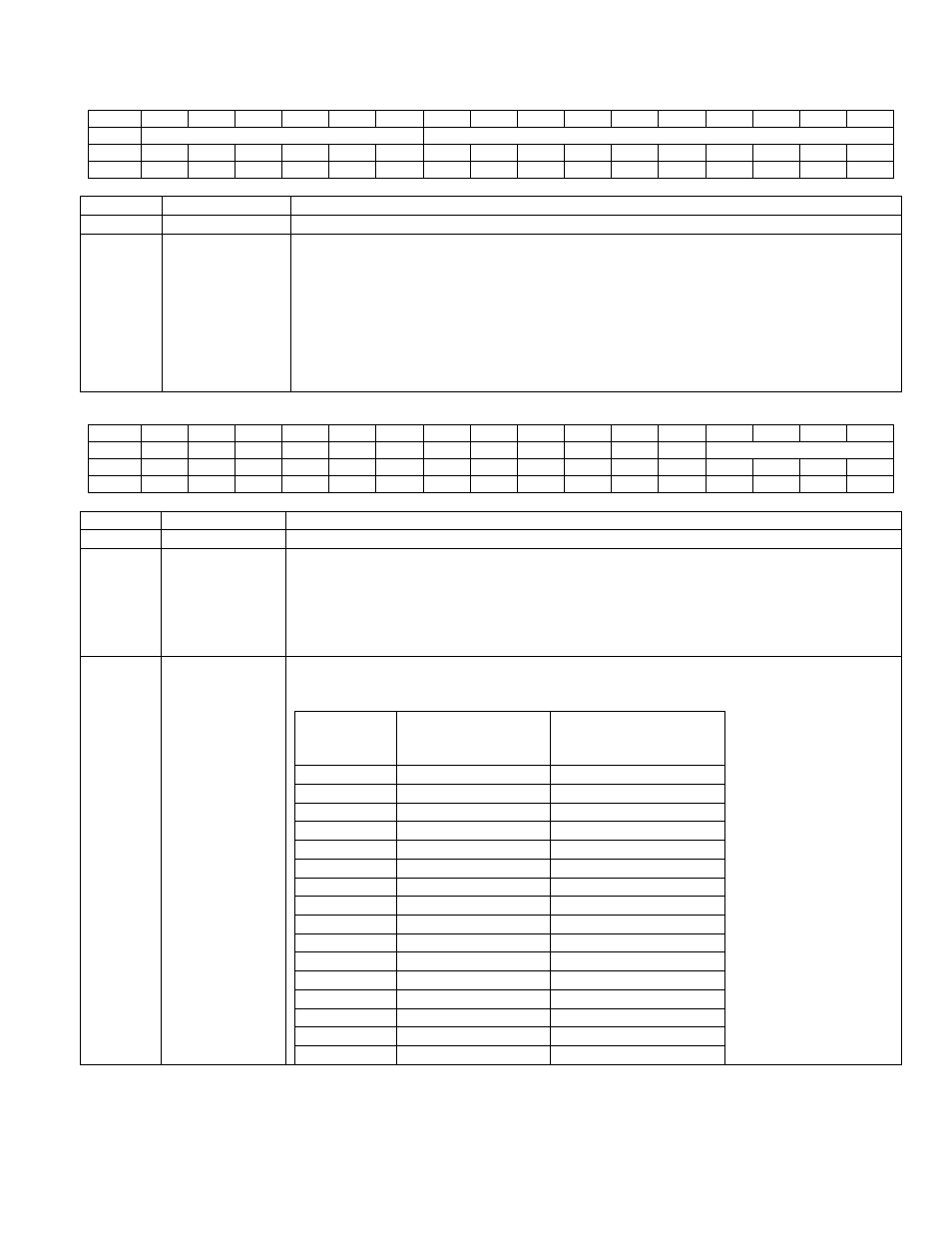
QTDATA Register map when RW_LST = 0 (in the QTCN Register)
Bit
15
14
13
12
11
10
9
8
7
6
5
4
3
2
1
0
Name
-
LOW or HIGH THRESHOLD
Reset
0
0
0
0
0
0
0
0
0
0
0
0
0
0
0
0
Access
r
r
r
r
r
r
rw
rw
rw
rw
rw
rw
rw
rw
rw
rw
BIT
NAME
DESCRIPTION
15:10
-
Reserved. The user should write these bits to ‘0’.
9:0
QTDATA[9:0]
a. Low Threshold Configuration (When the LTHT bit in the QTCN register is set to ‘0’)
The QTDATA register selects low threshold register addressed by QTIDX[3:0] bits in
the QTCN register for read and write operation. The low threshold registers are 10-bit
wide and the upper QTDATA [15:10] bits are ignored and return 0.
b. High Threshold Configuration (When the LTHT bit in the QTCN register is set to ‘1’)
The QTDATA selects high threshold register addressed by QTIDX[3:0] bits in the
QTCN register for read and write operation. The high threshold registers are 10-bit
wide and upper QTDATA [15:10] bits are ignored and return 0.
QTDATA Register map when RW_LST = 1 (in the QTCN Register)
Bit
15
14
13
12
11
10
9
8
7
6
5
4
3
2
1
0
Name
-
-
-
-
-
-
-
-
-
-
-
DIFF
CHSEL[3:0]
Reset
0
0
0
0
0
0
0
0
0
0
0
0
0
0
0
0
Access
r
r
r
r
r
r
r
r
r
r
r
rw
rw
rw
rw
rw
BIT
NAME
DESCRIPTION
15:5
-
Reserved. The user should write these bits to ‘0’.
4
DIFF
Mode Selection (DIFF
):
This bit selects the Quick trip input channel source either as
single-ended or differential mode. When this bit is set to ‘0’, quick trip channel
(addressed by CHSEL[3:0]) is selected as “single-ended” input. When this bit is set to
‘1’, quick trip channel (addressed by CHSEL[3:0]) is selected as “Differential Mode”
input. See the below table for various quick trip input channel configuration in single-
ended as well as differential mode.
3:0
CHSEL
[3:0]
QT Channel Select (CHSEL
[3:0]):
These bits select the Quick trip input channel
source for the quick trip list configuration.
CHSEL[3:0]
DIFF = 0
Channel Selected
Single-Ended
DIFF = 1
Channel Selected
Differential Mode
0000
ADC-S0
ADC-D0P – ADC-D0N
0001
ADC-S1
ADC-D1P – ADC-D1N
0010
ADC-S2
ADC-D2P – ADC-D2N
0011
ADC-S3
ADC-D3P – ADC-D3N
0100
ADC-S4
ADC-D4P – ADC-D4N
0101
ADC-S5
ADC-D5P – ADC-D5N
0110
ADC-S6
ADC-D6P – ADC-D6N
0111
ADC-S7
ADC-D7P – ADC-D7N
1000
ADC-S8
NOT VALID
1001
ADC-S9
NOT VALID
1010
ADC-S10
NOT VALID
1011
ADC-S11
NOT VALID
1100
ADC-S12
NOT VALID
1101
ADC-S13
NOT VALID
1110
ADC-S14
NOT VALID
1111
ADC-S15
NOT VALID