2 – i2c slave controller register description, 2 – i, C slave controller register description – Maxim Integrated DS4830A Optical Microcontroller User Manual
Page 103: Ds4830a user’s guide
DS4830A User’s Guide
103
11.2 – I
2
C Slave Controller Register Description
Following are the registers that are used to control the I
2
C Slave Interface.
11.2.1 – I
2
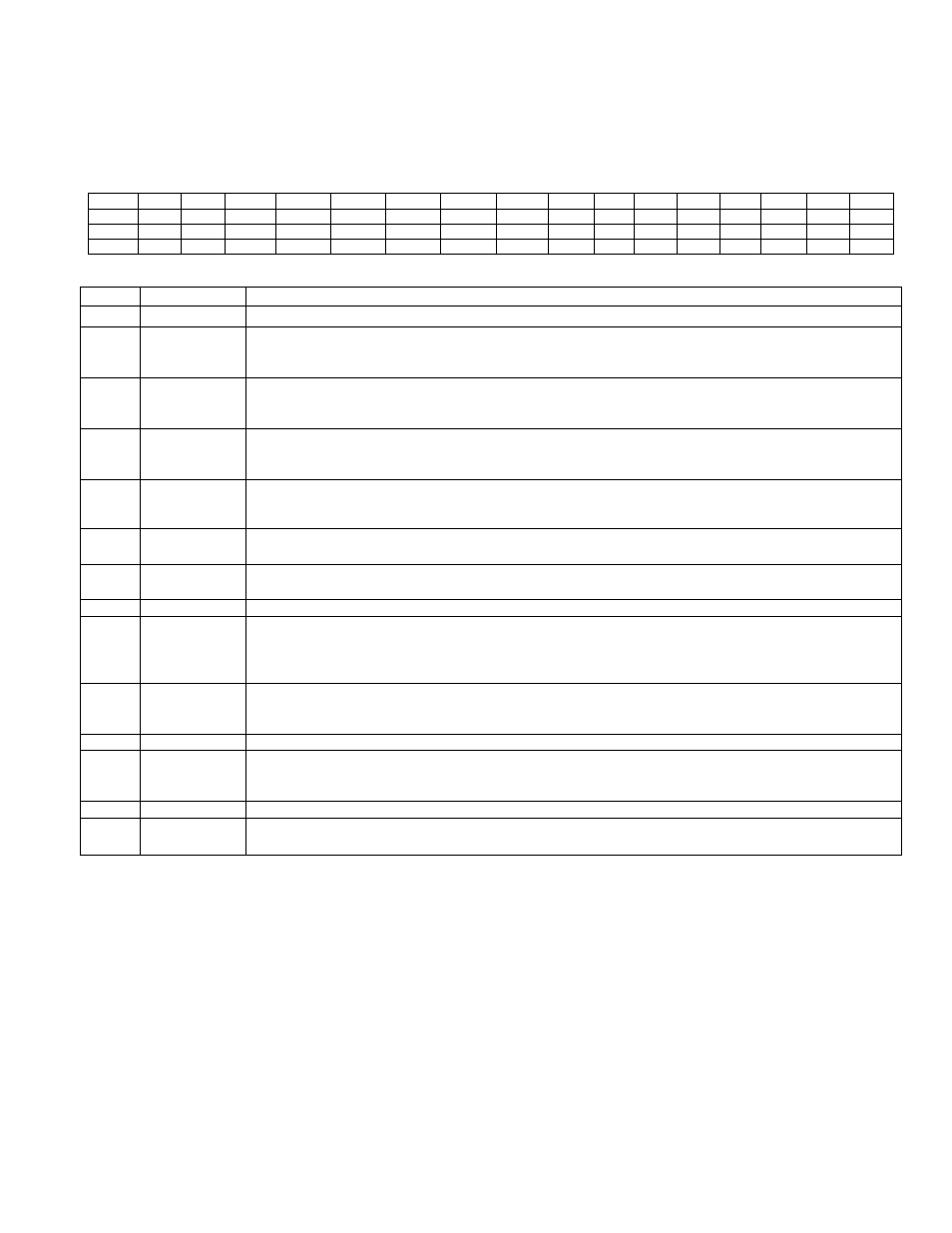
C Slave Control Register (I2CCN_S)
Bit
15
14
13
12
11
10
9
8
7
6
5
4
3
2
1
0
Name
-
-
ADDR4EN ADDR3EN ADDR2EN SMB_MOD
I2CSTREN I2CGCEN
-
-
I2CACK I2CSTRS
-
I2CMODE
-
I2CEN
Reset
0
0
0
0
0
0
0
0
0
0
0
0
0
0
0
1
Access
r
r
rw
rw
rw
rw
rw*
rw*
r
r
rw*
rw*
r
r
r
rw*
* Unrestricted Read. Unrestricted write access when I2CBUSY=0. Writes to I2CEN are disabled when I2CBUSY=1.
BIT
NAME
DESCRIPTION
15:14
Reserved
Reserved. The user should not write to these bits.
13
ADDR4EN
I
2
C
Slave Address 4 Enable: Setting this bit to ‘1’, enables slave address I2CSLA4_S and the
I
2
C
controller uses this slave address during the address match event. When this bit is set to ‘0’, disables
slave address I2CSLA4_S.
12
ADDR3EN
I
2
C
Slave Address 3 Enable: Setting this bit to ‘1’, enables slave address I2CSLA3_S and the
I
2
C
controller uses this slave address during the address match event. When this bit is set to ‘0’, disables
slave address I2CSLA3_S.
11
ADDR2EN
I
2
C
Slave Address 2 Enable: Setting this bit to ‘1’, enables slave address I2CSLA2_S and the
I
2
C
controller uses this slave address during the address match event. When this bit is set to ‘0’, disables
slave address I2CSLA2_S.
10
SMB_MOD
Slave SMBUS Mode Operation. When this bit is set to a ‘1’, SMBus timeout functionality is enabled
for the I2C slave interface. When this bit is cleared to ‘0’, the SMBus timeout functionality is disabled.
See the SMBUS Timeout section for more details.
9
I2CSTREN
I
2
C
Slave Clock Stretch Enable. Setting this bit to '1' stretches the clock (holds SCL low) at the end
of the clock cycle specified in I2CSTRS. Clearing this bit disables clock stretching.
8
I2CGCEN
I
2
C
Slave General Call Enable. Setting this bit to '1' enables the
I
2
C
to respond to a general call
address (address = 0000 0000). Clearing this bit to '0' disables response to general call address.
7:6
Reserved
Reserved. The user should not write to these bits.
5
I2CACK
I
2
C
Slave Data Acknowledge Bit. This bit selects the acknowledge bit returned by the
I
2
C
controller
while acting as a receiver. Setting this bit to ‘1’ generates a NACK (leaving SDA high). Clearing the
I2CACK bit to ‘0’ generates an ACK (pulling SDA LOW) during the acknowledgement cycle. This bit
retains its value unless changed by software or hardware.
4
I2CSTRS
I
2
C
Slave Clock Stretch Select. Setting this bit to ‘1’ enables clock stretching after the falling edge of
the 8
th
clock cycle. Clearing this bit to ‘0’ enables clock stretching after the falling edge of the 9
th
clock
cycle. This bit has no effect when clock stretching is disabled (I2CSTREN=0).
3
Reserved
Reserved. The user should not write to this bit.
2
I2CMODE
I
2
C
Transfer Mode Select. This bit reflects the actual R/
W bit value in current
I
2
C
transfer and is set
by hardware. The same bit is set by hardware for corresponding slave address register following a
successful slave address match.
1
Reserved
Reserved. The user should not write to this bit.
0
I2CEN
I
2
C
Slave Enable. This bit enables the
I
2
C
Slave function. When set to ’1’,
I
2
C
Slave communication
is enabled. When cleared to ‘0’, the
I
2
C
function is disabled.