Ds4830a user’s guide – Maxim Integrated DS4830A Optical Microcontroller User Manual
Page 154
DS4830A User’s Guide
154
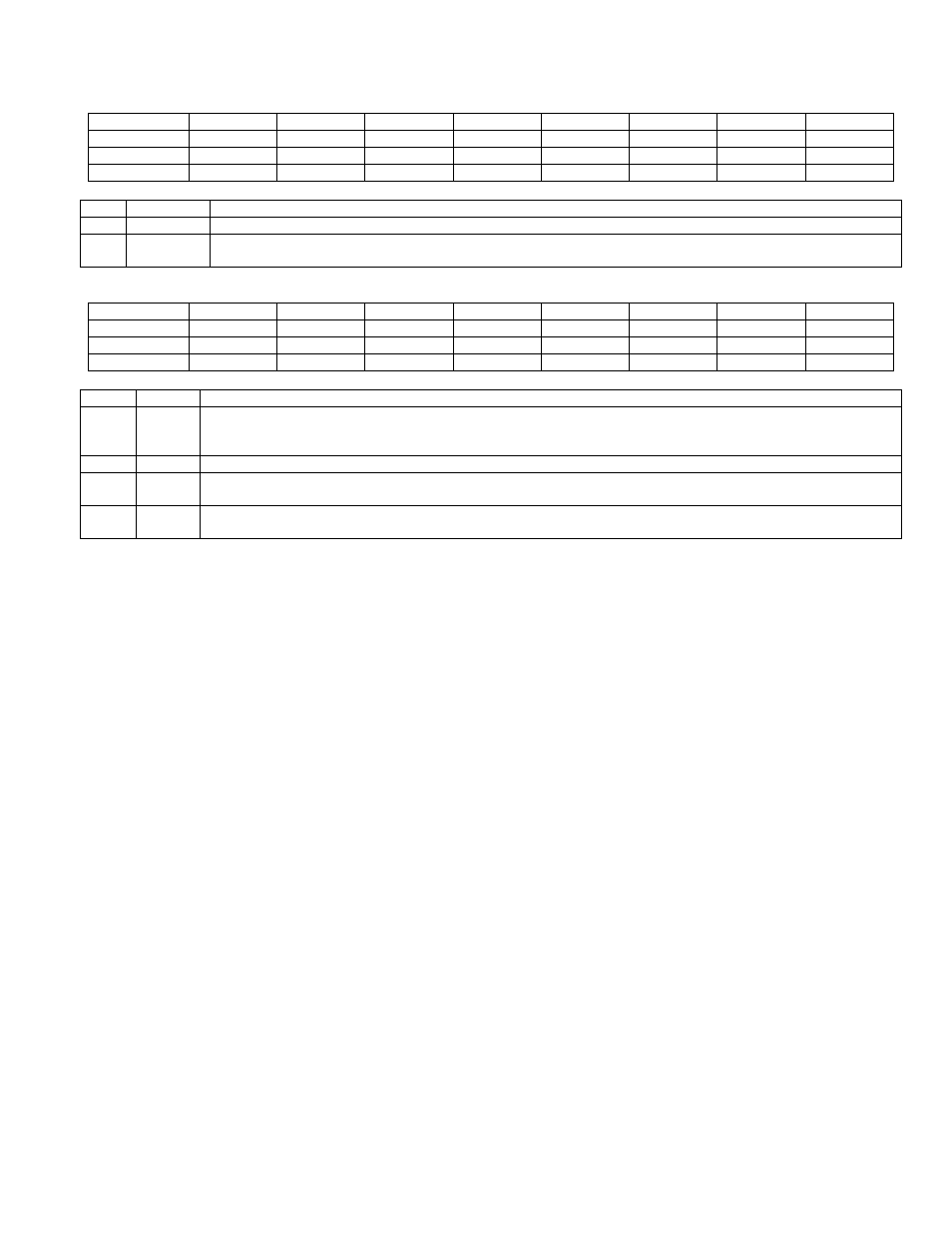
18.5.9 – MAC Select Register (MACSEL)
Bit
7
6
5
4
3
2
1
0
Name
-
-
-
-
-
-
-
MACRSEL
Reset
0
0
0
0
0
0
0
0
Access
r
r
r
r
r
r
r
rw
BIT
NAME
DESCRIPTION
7:1
-
Reserved
0
MACRSEL MAC Registers Select Register. The device has internally two sets of MAC registers. Using this bit one of
two MAC registers is selected which allows uninterruptible MAC operation.
18.5.10 – MAC Shift Register (SHIFT)
Bit
7
6
5
4
3
2
1
0
Name
SHC
-
-
-
-
-
SR
SL
Reset
0
0
0
0
0
0
0
0
Access
rw
r
r
r
r
r
rw
rw
BIT
NAME
DESCRIPTION
7
SHC
Shift Carry: This bit represents the carry out from last shift operation. For a left shift operation this bit will get
MC2[15] (MSB of MC2 register). For a right shift operation this bit will get MC0[0] (LSB of MC0 register). This
bit can be cleared by writing a 0 to it.
6:2
-
Reserved
1
SR
Shift Right: a 1 to this bit will cause one bit right shift operation on MC2-M0 register. This bit auto clears itself,
so a read on SHFT register will always return 0 for this bit position.
0
SL
Shift Left: a 1 to this bit will cause one bit left shift operation on MC2-M0 register. This bit auto clears itself, so
a read on SHFT register will always return 0 for this bit position.
The shift (right/left) operations are implemented for faster fixed point math operations. These operations only work
on the 48-bit accumulator, MC [2:0] registers. The MCR [1:0] registers are not affected by a shift operation.
Right Shift Operation:
On doing a right shift the MC2-MC0 contents will be
MC2[15:0] = MC2[15],MC2[15:1] (MSB bit, sign bit, is preserved)
MC1[15:0] = MC2[0],MC1[15:1]
MC0[15:0] = MC1[0],MC0[15:1]
SHC = MC0[0]
Left Shift Operation:
On doing a left shift the MC2-MC0 contents will be
SHC = MC2[15]
(shifted sign bit)
MC2[15:0] = MC2[14:0],MC1[15]
MC1[15:0] = MC1[14:0],MC0[15]
MC0[15:0] = MC0[14:0], 0