Ds4830a user’s guide, Frequency clock pwm frequency frame pwm 2 – Maxim Integrated DS4830A Optical Microcontroller User Manual
Page 135
DS4830A User’s Guide
135
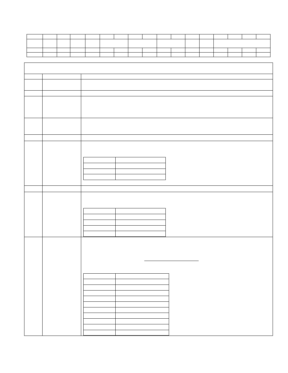
14.3.2.2 – Local Register PWMCFGn (through PWMDATA [15:0]
Bit
15
14
13
12
11
10
9
8
7
6
5
4
3
2
1
0
Name
INV
-
ALT_
LOC
PWMEN
-
CLK_SEL
-
PS1
PS0
RES[3:0]
Reset
0
0
0
0
0
0
0
0
0
0
0
0
0
0
0
0
Access
rw
rw
rw
rw
rw
rw
rw
rw
rw
rw
rw
rw
rw
rw
rw
rw
PWMCN REG_SEL = 01b
PWMDATA[15:0]
PWMCFGn[15:0]
BIT
NAME
DESCRIPTION
15
INV
Invert PWM Output. When this bit is set to ‘1’, PWM output is inverted for the selected
PWM channel (determined by the PWM_SEL[3:0] bits).
14
-
Reserved. The user should not write to this bit.
13
ALT_LOC
Alternate Location: PWM outputs at channels 0 to 7 are multiplexed with the DAC
outputs. By default, the PWM outputs appear at the DAC outputs. When ALT_LOC bit is
set to ‘1’, the PWM outputs will appear at the alternate location (See Table 14-3 for
details).
12
PWMEN
Local Enable: Setting this bit to ‘1’ will enable the individual PWM channel. PWM
operation will be enabled only when both local enable and the Master Enable M_EN in
PWMCN are enabled. Setting this bit to ‘0’ will disable the individual PWM channel.
11:10
-
Reserved. The user should not write to these bits.
9:8
CLK_SEL[1:0]
Clock Select. These bits select the PWM clock for the selected PWM channel (which is
selected by PWM_SEL[3:0] bits).
CLK_SEL
PWM Clock Source
00b
Core Clock
01b
Peripheral Clock
1xb
External Clock
The external clock range is 20MHz to 133MHz.
7:6
-
Reserved. The user should not write to these bits.
5:4
PS[1:0]
Pulse Spreading: These bits enable pulse spreading. The number of slots in a PWM
frame is defined by these bits along with resolution.
PS[1:0]
Pulse spreading
00b
Resolution / 2
10
01b
Resolution / 2
9
10b
Resolution / 2
8
11b
Resolution / 2
7
3:0
RES[3:0]
Resolution Select. These bits are used to configure PWM resolution (in bits) for selected
PWM channel (which is selected by PWM_SEL[3:0] bits). The PWM Frame frequency is
determined by the clock Frequency programmed and the resolution selected.
N
Frequency
Clock
PWM
Frequency
Frame
PWM
2
=
Where N is the selected resolution.
RES [3:0]
PWM Resolution bits
0000b
7
0001b
8
0010b
9
0011b
10
0100b
11
0101b
12
0110b
13
0111b
14
1000b
15
>=1001b
16