8 – watchdog control register (wdcn, 08h[0fh]), 9 – accumulator n register (a[n], 09h[nh]), 10 – prefix register (pfx[n], 0bh[n – Maxim Integrated DS4830A Optical Microcontroller User Manual
Page 29
DS4830A User’s Guide
29
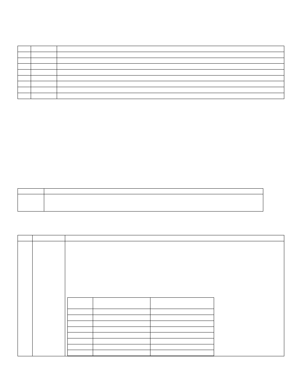
3.7 – Interrupt Identification Register (IIR, 08h[0Bh])
Initialization: This register is cleared to 00h on all forms of reset.
Access: Read only.
Bit
Name
Function
7
IIS
Interrupt Identifier Flag for System Modules
6
Reserved Reserved. All reads return 0.
5
II5
Interrupt Identifier Flag for Register Module 5
4
II4
Interrupt Identifier Flag for Register Module 4
3
II3
Interrupt Identifier Flag for Register Module 3
2
II2
Interrupt Identifier Flag for Register Module 2
1
II1
Interrupt Identifier Flag for Register Module 1
0
II0
Interrupt Identifier Flag for Register Module 0
The first six bits in this register indicate interrupts pending in modules 0 to 5, one bit per module. The eighth bit, IIS,
indicates a pending system interrupt, such as from the watchdog timer. The interrupt pending flags will be set only for
enabled interrupt sources waiting for service. The interrupt pending flag will be cleared when the pending interrupt
sources within that module are disabled or when the interrupt flags are cleared by software
3.8 – Watchdog Control Register (WDCN, 08h[0Fh])
Initialization: Bits 5, 4, 3 and 0 are cleared to 0 on all forms of reset; for others, see individual bit descriptions.
Access: Unrestricted direct read/write access.
See the watchdog section for WDCN register description and further detail.
3.9 – Accumulator n Register (A[n], 09h[nh])
Initialization: These registers are cleared to 0000h on all forms of reset.
Access: Unrestricted direct read/write access.
BIT
DESCRIPTION
A[n][15:0]
These registers (n=0 to 15) act as the accumulator for all ALU arithmetic and logical operations
when selected by the accumulator pointer (AP). They can also be used as a general-purpose
working register.
3.10 – Prefix Register (PFX[n], 0Bh[n]
)
Initialization: This register is cleared to 0000h on all forms of reset.
yAccess: Unrestricted direct read/write access.
BIT
NAME
DESCRIPTION
15:0 PFX[n][15:0]
The Prefix register provides a means of supplying an additional 8 bits of high-order data for use by
the succeeding instruction as well as providing additional indexing capabilities. This register will
only hold any data written to it for one execution cycle, after which it will revert to 0000h. Although
this is a 16-bit register, only the lower 8 bits are actually used for prefixing purposes by the next
instruction. Writing to or reading from any index in the Prefix module will select the same 16-bit
register. However, when the Prefix register is written, the index n used for the PFX[n] write also
determines the high-order bits for the register source and destination specified in the following
instruction.
The index selection reverts to 0 (default mode allowing selection of registers 0h to 7h for
destinations) after one cycle in the same manner as the contents of the Prefix register.
WRITE
TO
SOURCE REGISTER
RANGE
DESTINATION
REGISTER RANGE
PFX[0]
0h to Fh
0h to 7h
PFX[1]
10h to 1Fh
0h to 7h
PFX[2]
0h to Fh
8h to Fh
PFX[3]
10h to 1Fh
8h to Fh
PFX[4]
0h to Fh
10h to 17h
PFX[5]
10h to 1Fh
10h to 17h
PFX[6]
0h to Fh
18h to 1Fh
PFX[7]
10h to 1Fh
18h to 1Fh