Ds4830a user’s guide – Maxim Integrated DS4830A Optical Microcontroller User Manual
Page 163
DS4830A User’s Guide
163
commands and data can be exchanged between the host and the DS4830A by operating in the data register portion
of the state sequence (i.e. DR-Scan). The TAP retains the private instruction which was loaded into IR2:0 until a new
instruction is shifted in or until the TAP controller returns to the Test-Logic-Reset state.
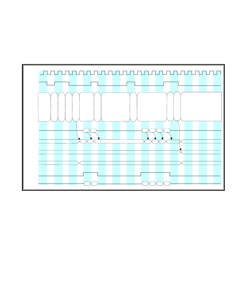
20.3.1 – TAP Communication Examples – IR-Scan and DR-Scan
Figures 20-3 and 20-4 illustrate examples of communication between the host JTAG controller and the Test Access
Port (TAP) of the DS4830A. The host controls the TCK and TMS signals to move through the desired TAP states
while accessing the selected shift register through the TDI input and TDO output pair.
R
u
n
-T
e
s
t/I
d
le
U
p
d
a
te
-IR
E
x
it1
-IR
P
a
u
s
e
-IR
E
x
it2
-IR
S
h
ift
-IR
E
x
it1
-IR
S
e
le
c
t-
D
R
-S
c
a
n
New Instruction
Instruction Register
T
e
s
t-
L
o
g
ic
-R
e
s
e
t
TCK
TMS
TDI
TDO
Control
State
IR Shift
Register
IR Parallel
Output
Register
Selected
TDO
Enable
C
a
p
tu
re
-IR
S
h
ift
-IR
S
e
le
c
t-
IR
-S
c
a
n
R
u
n
-T
e
s
t/I
d
le
By-Pass
Don’t care or undefined
Don’t care or undefined
Don’t care or undefined
Don’t care or undefined
Figure 20-3: TAP Controller Debug Mode IR-Scan Example