Ds4830a user’s guide – Maxim Integrated DS4830A Optical Microcontroller User Manual
Page 109
DS4830A User’s Guide
109
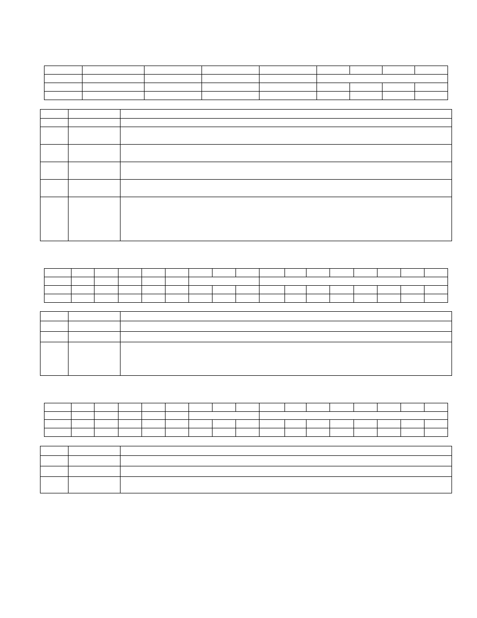
11.2.12 – Current Slave Address Register (CUR_SLA)
Bit
7
6
5
4
3
2
1
0
Name
MADDR_EN14
MADDR_EN3
MADDR_EN2
MADDR_EN1
SLA[3:0]
Reset
0
0
0
0
0
0
0
0
Access
rw
rw
rw
rw
rw
rw
rw
rw
BIT
NAME
DESCRIPTION
15:8
Reserved
Reserved. The user should not write to these bits.
7
MADDR_EN4
Memory Address Detection Enable 4: Setting this bit to ‘1’, enables the memory address detection as
described in section
11.1.6.3
for the slave address defined by the I2CSLA4_S register.
6
MADDR_EN3
Memory Address Detection Enable 3: Setting this bit to ‘1’, enables the memory address detection as
described in section
11.1.6.3
for the slave address defined by the I2CSLA3_S register.
5
MADDR_EN2
Memory Address Detection Enable 2: Setting this bit to ‘1’, enables the memory address detection as
described in section
11.1.6.3
for the slave address defined by the I2CSLA2_S register.
4
MADDR_EN1
Memory Address Det1ction Enable 1: Setting this bit to ‘1’ enables the memory address detection as
described in section
11.1.6.3
for the slave address defined by the for I2CSLA_S register.
3:0
SLA[3:0]
Slave Address Select. These bits indicate the current active slave address. These bits are updated
after the slave address match event by the
I
2
C controller
. Using these bits, the TX Pages are selected
by the
I
2
C
controller during the
I
2
C
transmits events. The
I
2
C
controller allows writing to these bits.
However, user should write to these bits before the address match event which allows
I
2
C controller to
select
intended TX page.
11.2.13 – Memory Address Pointer Register (MPNTR)
Bit
15
14
13
12
11
10
9
8
7
6
5
4
3
2
1
0
Name
-
-
-
-
-
PAGE[2:0]
MEM_PNTR[7:0]
Reset
0
0
0
0
0
0
0
0
0
0
0
0
0
0
0
0
Access
r
r
r
r
r
rw
rw
rw
rw
rw
rw
rw
rw
rw
rw
rw
BIT
NAME
DESCRIPTION
15:11
Reserved
Reserved. The user should not write to this bit.
10:8
PAGE
PAGE: These bits define the page of memory map structure for current active slave address.
7:0
MEM_ADDR
Memory Address. These bits store current address of memory map structure of the current active
slave address. The
I
2
C
controller automatically increments and performs boundary rollover for the
active slave address according to ROLLOVER bit (ROLLOVR) defined in the corresponding MADDR
register.
11.2.14 – Read Memory Address Pointer Register (RPNTR)
Bit
15
14
13
12
11
10
9
8
7
6
5
4
3
2
1
0
Name
-
-
-
-
-
PAGE[2:0]
MEM_PNTR[7:0]
Reset
0
0
0
0
0
0
0
0
0
0
0
0
0
0
0
0
Access
r
r
r
r
r
rw
rw
rw
rw
rw
rw
rw
rw
rw
rw
rw
BIT
NAME
DESCRIPTION
15:11
Reserved
Reserved. The user should not write to this bit.
10:8
PAGE
PAGE: These bits define the page of memory map structure for current active slave address.
7:0
MEM_ADDR
Memory Address. These bits maintain current read address of memory map structure for the current
active slave address and is used in word mode.
Writing 0000h to RPTNR will cause this register to update with a pointer to the current SRAM location to store data
based upon the memory location defined in the active slave address’ MADDR register and the captured memory
location.