A-190, System a - 100, Starting to use the a-190 – Doepfer A-100(~ 40 MB) User Manual
Page 658: Doepfer
A-190
MIDI-CV/SYNC Interface
System A - 100
doepfer
4
3. Starting to use the A-190
Before switching your system on, use a MIDI cable to
connect between your MIDI instrument and the A-190:
D
Connect the A-190’s input socket MIDI IN " to the
MIDI OUT socket of your MIDI instrument (master
keyboard, MIDI synth, MIDI sequencer, etc.).
D
Now switch your System A-100 on. The Gate LED
7
will briefly light up, to show you the A-190’s
software version (one blink = Version 1, etc.).
D
Patch the outputs of your A-190 to corresponding
modules on the System A-100:
H
The gate output % and CV1 output & are automa-
tically connected to the system bus of the A-100, so
don’t use patch cables to connect these, unless you
have cut the links, or wish to connect to a module
whose system bus isn’t connected with the A-190’s
(have a look at the note on using more than one
A-190). VCOs on the same system bus automati-
cally receive CV1, and ADSRs automatically re-
ceive the gate signal.
D
Use the CONFIG and PERFORM menus to tailor
the MIDI set-up to your requirements.
A
N.B. if you’re using more than one A-190:
The A-190 is normally connected up to the INT.CV und
INT.GATE on the system bus.
If you want to run more than one A-190 with only a
single system bus, then only one of the A-190s must be
connected to the system bus.
Disconnect the other A-190 modules from the system
bus, by cutting the two links labelled CV1 and GATE
(near the bus ribbon connector on the A-190 board).
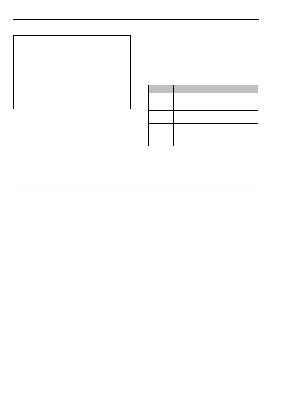
Output
Connection notes
/
CV 2
Any module’s CV input (for instance a
VCF’s CV input, for controlling the filter
cut-off point).
§
Clock
For instance, the A-160’s trigger input for
MIDI-synced sequences.
$
Reset
The A-160’s reset input, for MIDI control of
start and stop messages;
the A-140’s gate or retrigger input for
MIDI-synchronised envelopes.