A-134, System a - 100, Doepfer – Doepfer A-100(~ 40 MB) User Manual
Page 358
A-134
Voltage Controlled Panning
System A - 100
doepfer
4
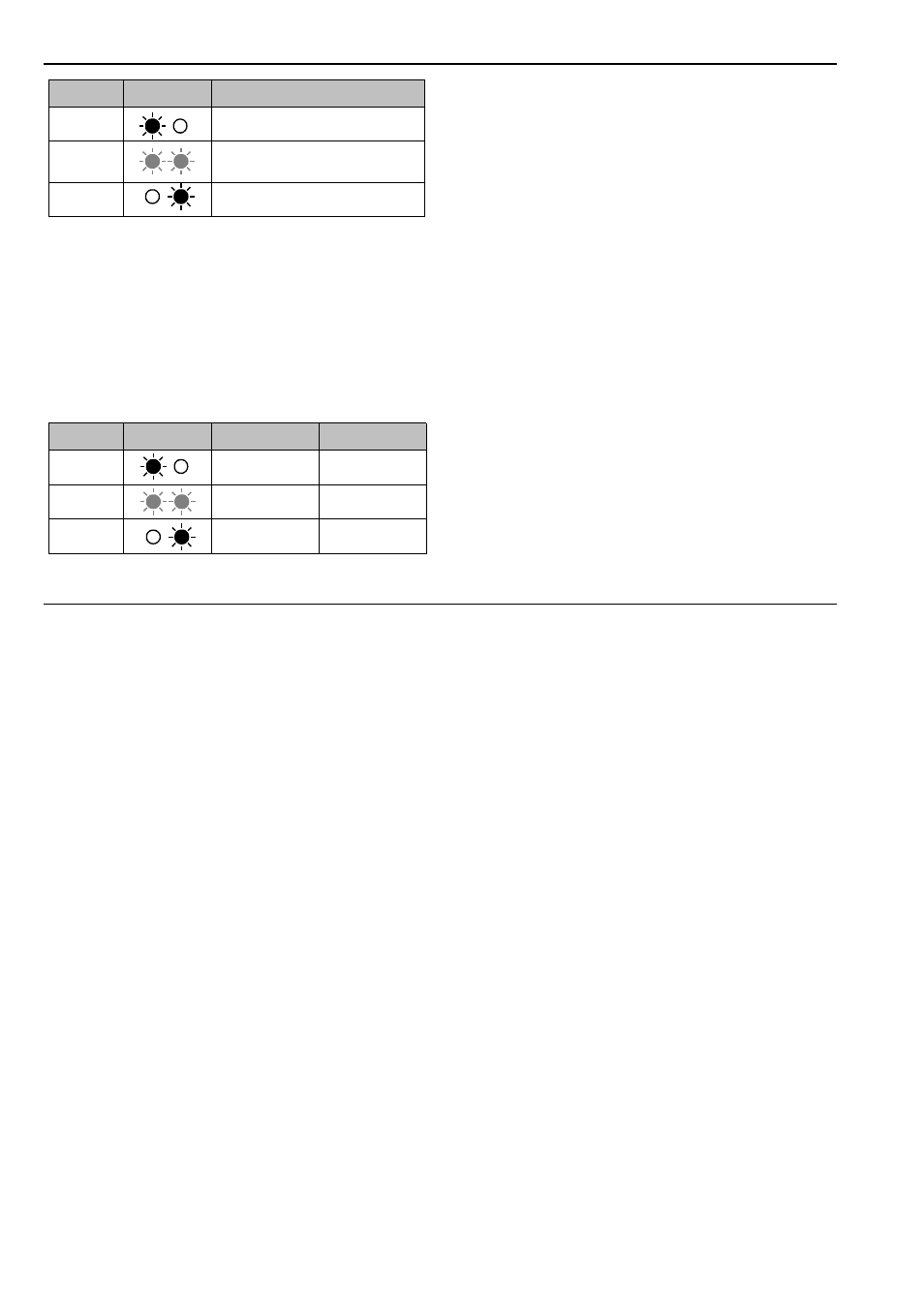
Table 1: Input mixing mode
Output panning mode:
In this mode, the left LED monitors the left audio out-
put %, the right LED the right audio output /. The
LEDs indicate the relative position in the stereo
soundstage produced by the two audio outputs. Ta-
ble 2 shows the result of differing control voltages or
positioning of the Pan control.
Table 2: Output panning mode
2
Pan
Control 2 is used to control the relative signal levels
at outputs %, & and /. In input mixing mode, you
control the relative amounts of each of the input si-
gnal present at the Mix output; in output panning
mode this determines the position in the stereo
soundstage.
3
CV 2
Attenuator 3 is used to adjust the level of control
voltage present at CV input " .
4
Lev 1 • 5 Lev 2
The level of the audio signals at inputs § and $ is
controlled by attenuators 4 and 5 .
Pan
LEDs
Mix Output
0
Just the signal from Audio In 1
5
Equal amounts of signal from
Audio In 1 and Audio In 2
10
Just the signal from Audio In 2
Pan
LEDs
Left Output
Right Output
0
100 %
0 %
5
50 %
50 %
10
0 %
100 %