System a - 100, A-167, User examples – Doepfer A-100(~ 40 MB) User Manual
Page 567: Doepfer
doepfer
System A - 100
CMP
A-167
5
5. In - / Outputs
!
+ IN
The input signal fed into this socket is attenuated with
control 1 and added to the internal voltage (U
SUM
).
"
- IN
The input signal fed into this socket is attenuated with
control 2 and subtracted from the internal voltage
(U
SUM
).
§
Analog Sum
At this socket the internal voltage U
SUM
is available
(see chapter 3).
$
Cmp. Out • % Inv. Cmp. Out
The Gate output $ is "high" (~ +10V) if the internal
voltage U
SUM
is positive. Otherwise it is "low" (~ 0V).
The inverted Gate output % always has the opposite
state of the normal gate output $. Consequently this
output is "low" if the internal voltage U
SUM
is positive.
Otherwise it is "high".
6. User examples
The main application of module A-167 is the genera-
tion of gate signals depending upon analog volta-
ges, e.g. a gate signal that depends upon the present
value of a LFO (triangle), ADSR or random signal can
be generated and used to control a voltage controlled
switch that on the other hand switches different control
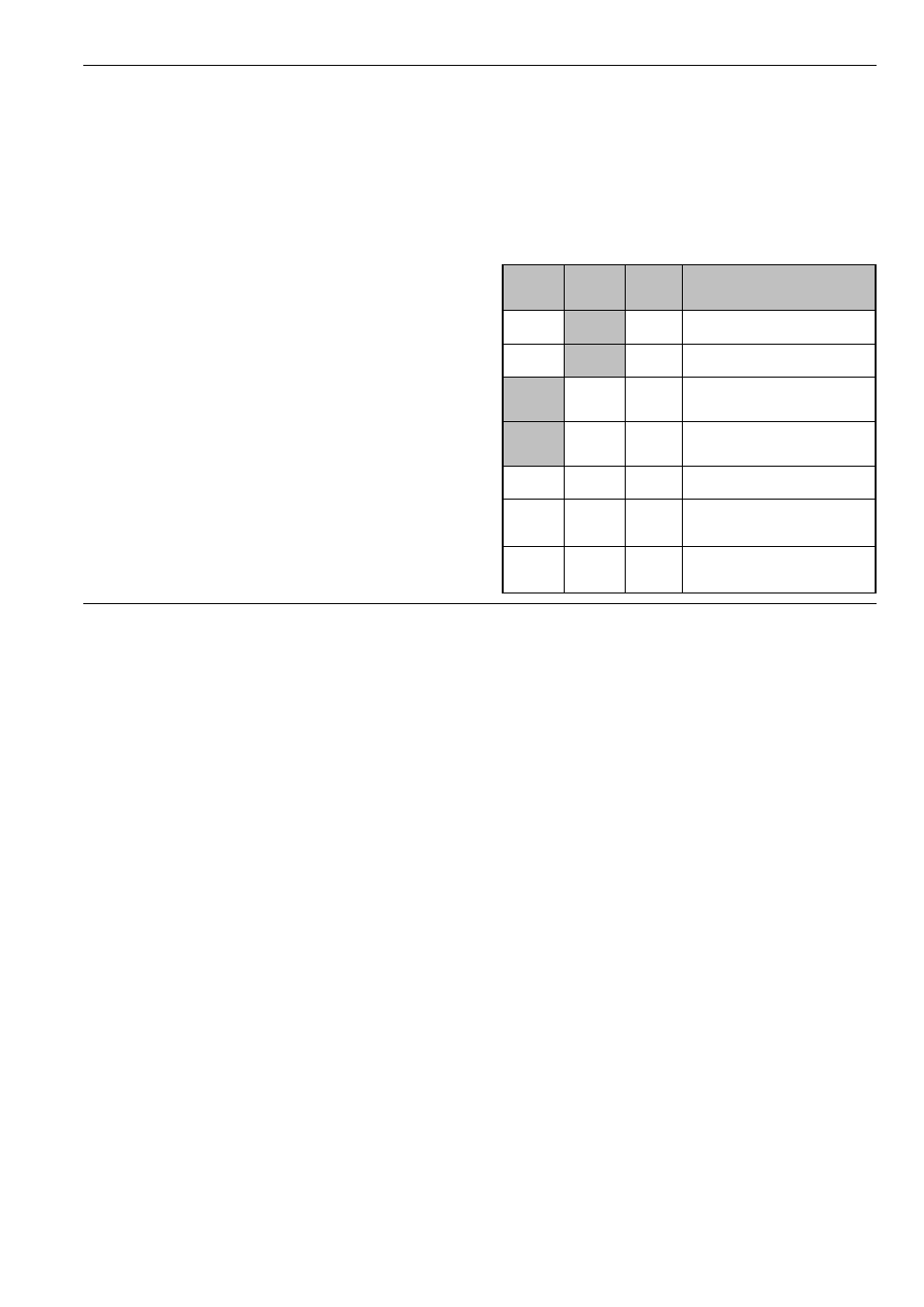
voltages or audio signals. More examples shows the
following table:
Signal
at + In
Signal
at - In
Offset
Meaning concerning
U
SUM
at §
•
> 0
(positive) offset generator
•
< 0
(negative) offset generator
•
> 0
(positive) inverting offset
generator
•
< 0
(negative) inverting offset
generator
•
•
0
subtractor
•
•
> 0
subtractor + (positive) off-
set generator
•
•
< 0
subtractor + (negative) off-
set generator