Doepfer, Rahm en 1 rahm en 2 rahm en 3 – Doepfer A-100(~ 40 MB) User Manual
Page 17
doepfer
System A - 100
3. A-100 signal flow
11
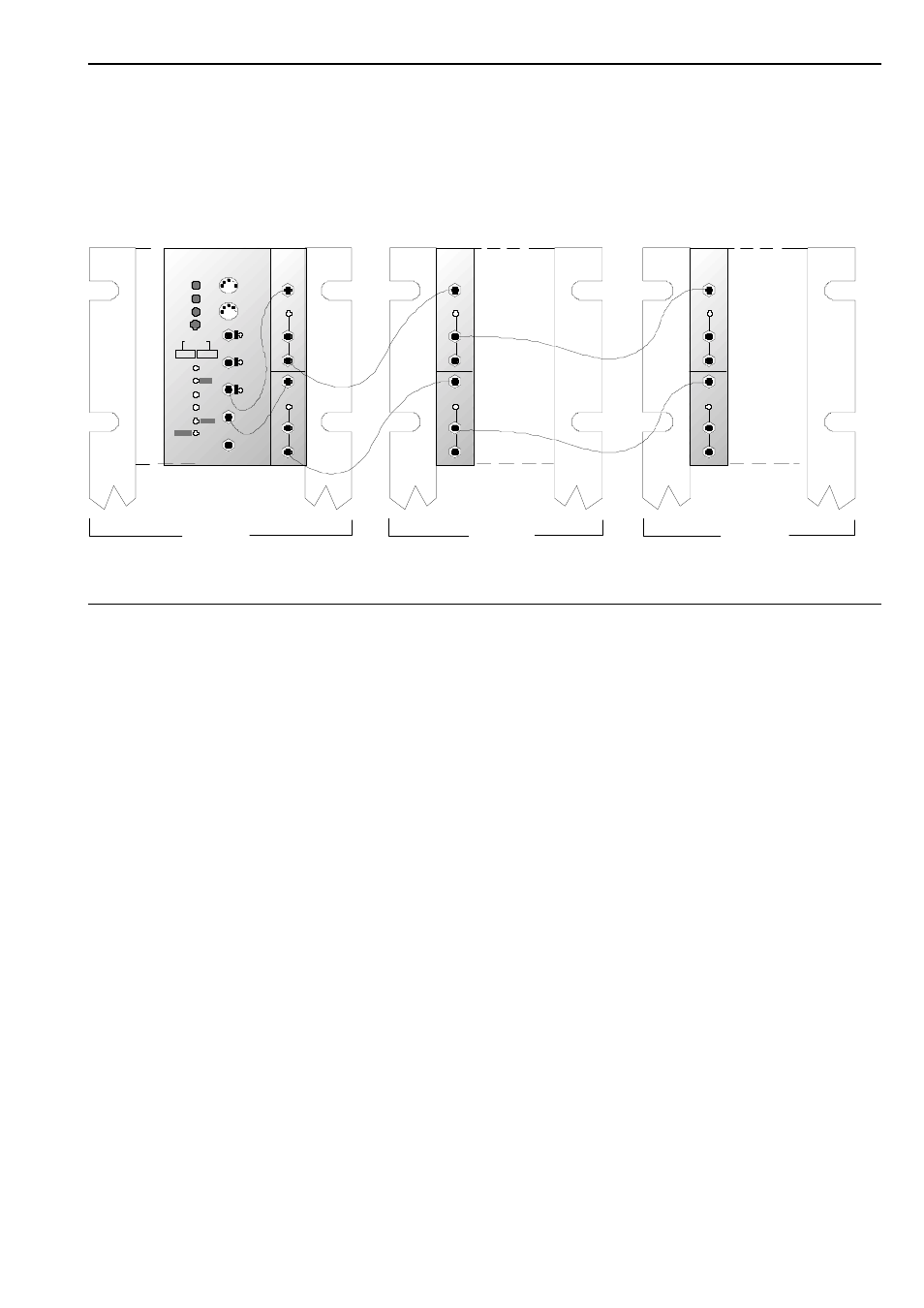
If your A-100 consists of more than one case only you
may want to have a common CV and/or Gate bus
available. For this application the bus access modules
A-185-1 or A-185-2 are planned. These modules have
access to the bus an are able to "send" CV and/or
Gate to the bus.
A
Important note:
If the bus access modules A-185-1 or A-185-2 are
used no other CV or Gate "transmitter" must be instal-
led on the same bus ! Otherwise a short circuit bet-
ween the different CV or Gate outputs would be made
via the bus.
doepfer
System A - 100
3. A-100 signal flow
A-185
BUS ACCESS
G ate
I n
C ontr.
C V
I n
CV
O ut
C ontr.
G ate
O ut
G ate
O ut
CV
O ut
A-190
MCVS
G ro up
Me n u
I nc. /+
D ec . /-
M ID I
Thru
MI DI
In
R es e t
G ate
C V 1
C V 2
C lo ck
Channel
LFO Frq.
Glide
Assign
Arpeg.
CV 1
Offs et
Sc ale
CV 2
Group
Perform. Config.
!
"
MIDI -CV/SYNC INTERF.
A-185
BUS ACCESS
G ate
I n
C ontr.
C V
I n
CV
O ut
C ontr.
G ate
O ut
G ate
O ut
CV
O ut
A- 185
BUS ACCESS
G ate
I n
C ontr.
C V
I n
CV
O ut
C ontr.
G ate
O ut
G ate
O ut
CV
O ut
Rahm en 1
Rahm en 2
Rahm en 3
Fig 11: How to establish a common CV/Gate bus for several cases