A-101-2, System a - 100, Doepfer – Doepfer A-100(~ 40 MB) User Manual
Page 54
A-101-2
Vactrol Lowpass Gate
System A - 100
doepfer
4
4
Resonance (control)
In low pass mode this is the resonance control. The
resonance function "colors" to the sound and is ad-
justable all the way up to self-oscillation. Due to the
vactrol tolerances and tracking errors mentioned above
resonance resp. self-oscillation deviations over the fre-
quency range may occur.
In the VCA mode control 4 only changes the overall
loudness.
In the combined LP+VCA mode control 4 affects both
loudness and resonance.
The resonance function was not available for Buchla's
low pass gate. To reproduce the original Buchla sound
the resonance control simply has to be set fully counter-
clockwise.
$
Audio Out (socket)
This socket is the audio output of the module. According
to the selected mode the low pass filtered resp. ampli-
tude modulated input signal appears.
5
Function (toggle switch)
%
a G1 (socket) / %b G2 (socket)
This group of elements serves to select the desired
function resp. mode. These three functions are avai-
lable:
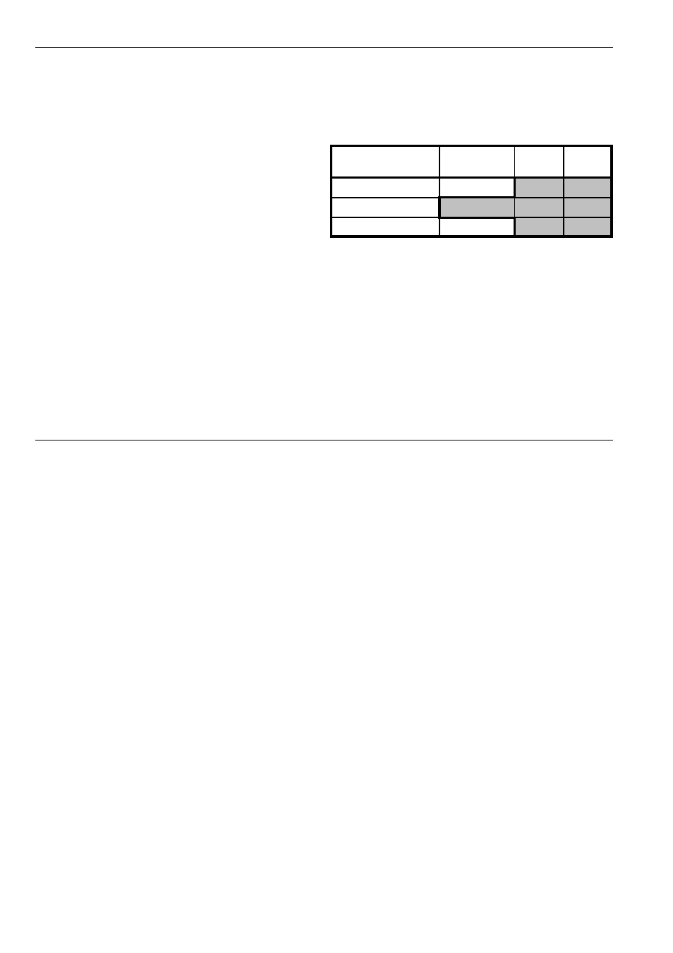
The function can be selected with the toggle switch 5 or
the two gate inputs %a G1 and %b G2. If the gate inputs
are used to selected the function the toggle switch has to
be in middle position L+V/Ext. (i.e. the grey shaded area
in the above table).
For the gate inputs "low" corresponds to a control vol-
tage range of about 0...+2V, "high" corresponds to about
+3...+12V.
Function
Switch
position
G1
G2
low pass
LP
high
low
low pass + VCA
L+V/Ext.
low
low
VCA
VCA
low
high