A-112, System a - 100, Doepfer – Doepfer A-100(~ 40 MB) User Manual
Page 202
A-112
Sampler
System A - 100
doepfer
12
H
During Data transmission via MIDI OUT the
MIDI input and gate are not scanned. There-
fore a new dump cannot be triggered by
mistake.
Gate = high:
As soon as the gate goes high (e.g. by pressing button
4
) the sample memory is transferred as a SysEx dump
via MIDI OUT and LED 3 turns on (same function as
sample dump request via MIDI in).
H
To trigger a sample dump manually a short
high gate level is sufficient. It is not neces-
sary to keep the gate level high.
• Wave dump mode
This mode is very similar to the normal dump mode
(see above). The difference from the normal dump
mode is that the data of a single wavetable (page) of
256 bytes is transferred instead of the complete
sampling memory of a bank.
The number of the wavetable is determined by the
position of the tune control 2 and the voltage applied
to CV input ".
• Delay mode
This mode generates a simple delay. The incoming
audio signal is delayed and passed to the audio out-
put.
H
The memory bank S2 is overwritten in this
mode!
Principle: The incoming audio signal is sampled and
written into a memory position in bank S2. Before this
the old value at this position is transferred to the audio
output. The number of the memory position is in-
creased by 1 and the process is repeated. When
reaching the last memory position the process starts at
memory position 1. The last memory position depends
upon the length (Len, see below).
5
5
5
5
6
6
6
6
7
7
7
7
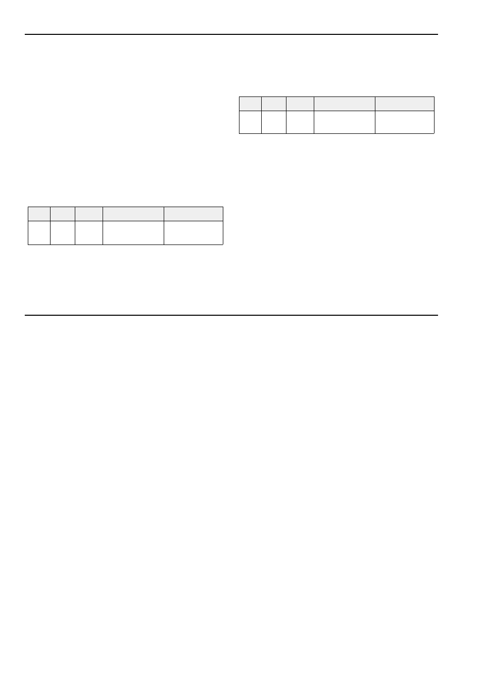
Audio / Wave-CV In
Tune / CV
S1,
S2
Dmp Wav
wave page num-
ber
5
5
5
5
6
6
6
6
7
7
7
7
Audio / Wave-CV In
Tune / CV
Eff
Del
Norm
audio signal
sampling fre-
quency