Doepfer MTC64 Output Board (transistor driver board) User Manual
Mtc64 driver board
MTC64 Driver Board
User's Manual
© 2004 by Doepfer Musikelektronik
Electronic basic knowledge is required to install the MTC64 driver board and to connect the
elements driven by the board. When you are not sure if your knowledge is sufficient please
consult an expert. We cannot take back modules that became defective because of wrong
installation or wrong connections. We also cannot take back modules which have been
soldered by the user.
The MTC64 outputs are able to drive only very small loads (max. 3 mA) at a very small output voltage
(about 4.5 V). Therefore an additional driver for each output is necessary as soon as more than 3mA
and/or more than 4.5V are required (refer to the last pages of the MTC64 user's manual). For that
purpose a special MTC64 driver board for 16 outputs each was developed. The driver permit currents
up to 0.5A without additional heat sinks resp. up to 1.5A with additional heat sinks that cool the
transistors, and voltages up to 40V.
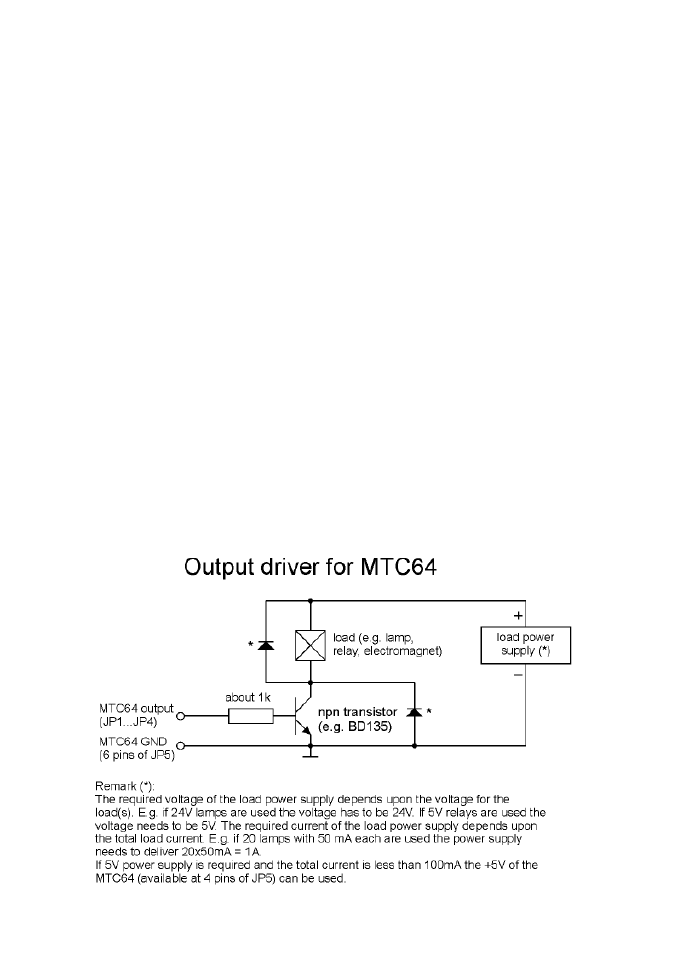
The schematics below shows one of the 16 identical transistor drivers. By means of the driver board
for example relays, incandescend lamps, magnets or DC motors can be controlled. Each load (i.e.
relay/lamp/magnet/motor....) is connected between the collector of the corresponding transistor (= one
of the output terminals of the driver board) and the positive terminal of the power supply for the loads.
The power supply has to be suitable for the loads in question. If you want to drive e.g. 16 lamps with
24V and 100mA each you need a power supply with 24V and at least 1.6A (16 x100mA = 1.6A).
The internal +5V of the MTC64 main baord can be used only if the loads can be driven with 5V and
the total current is less than 100mA. Otherwise the internal +5V of the MTC64 cannot be used as
power supply for the loads driven by the MTC64 output board !
In case that inductive loads (e.g. magnets, relays, motors) have to be switched, one of the protecting
diodes (marked with an asterisk in the schematics) is required. The diodes are alternatively, i.e. only
one is necessary. For relays the diodes may already be included with the relay (please refer to the
data sheet of the relay).
If loads above 500mA have to be switched some modifications have to be carried out: the 2k2 base
resistor of the switching transistors has to be reduced to about 270 Ohm .The shift register circuits
CD4094 at the main MTC64 board have to replaced by 74HC4094 as these are able to deliver a
higher current. From about 2005 all MTC64 basic boards will be equipped with 74HC4094.