System a - 100, A-136, Controls – Doepfer A-100(~ 40 MB) User Manual
Page 371: Doepfer
doepfer
System A - 100
Distortion / Waveshaper
A-136
3
3. Controls
1
A
Control 1 defines the amplification A of the original
signal. The range of the amplification factor is about
-4...+4. This means that one can obtain actual
amplification (range +1...+4), or attenuation (range
0...+1) or even inversion of the original signal (range
-4...0). The table below shows the approximate
assignment of some control settings and the
corresponding amplification factors:
Tab. 1: How control settings affect amplification
factors
2
+ L • 3 - L
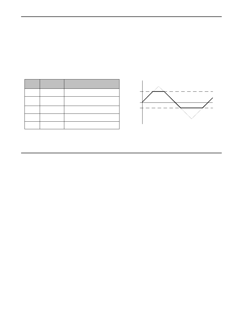
Controls 2 and 3 adjust the positive (+L) and
negative (-L) clipping levels respectively.
In the positive signal section only signal voltages
above the positive clipping level +L are affected by the
amplification control +A.
In the negative signal section only signal voltages
below the negative clipping level -L are affected by the
amplification control -A.
Fig. 1: how the clipping levels work (input signal =
triangle)
Control
setting
Amplification
factor
Explanation
0
about -4
maximum negative amplification
3,5
about -1
same amplitude as input signal but
inverted
5
about 0
suppression of input signal
6,5
about 1
same amplitude as input signal
10
about 4
maximum positive amplification
0
+ L
- L