System a - 100, Doepfer, Modular vocoder – Doepfer A-100(~ 40 MB) User Manual
Page 322: Using just the basic modules, Frequency displacement
A-129 /1/2
Modular Vocoder
System A - 100
doepfer
8
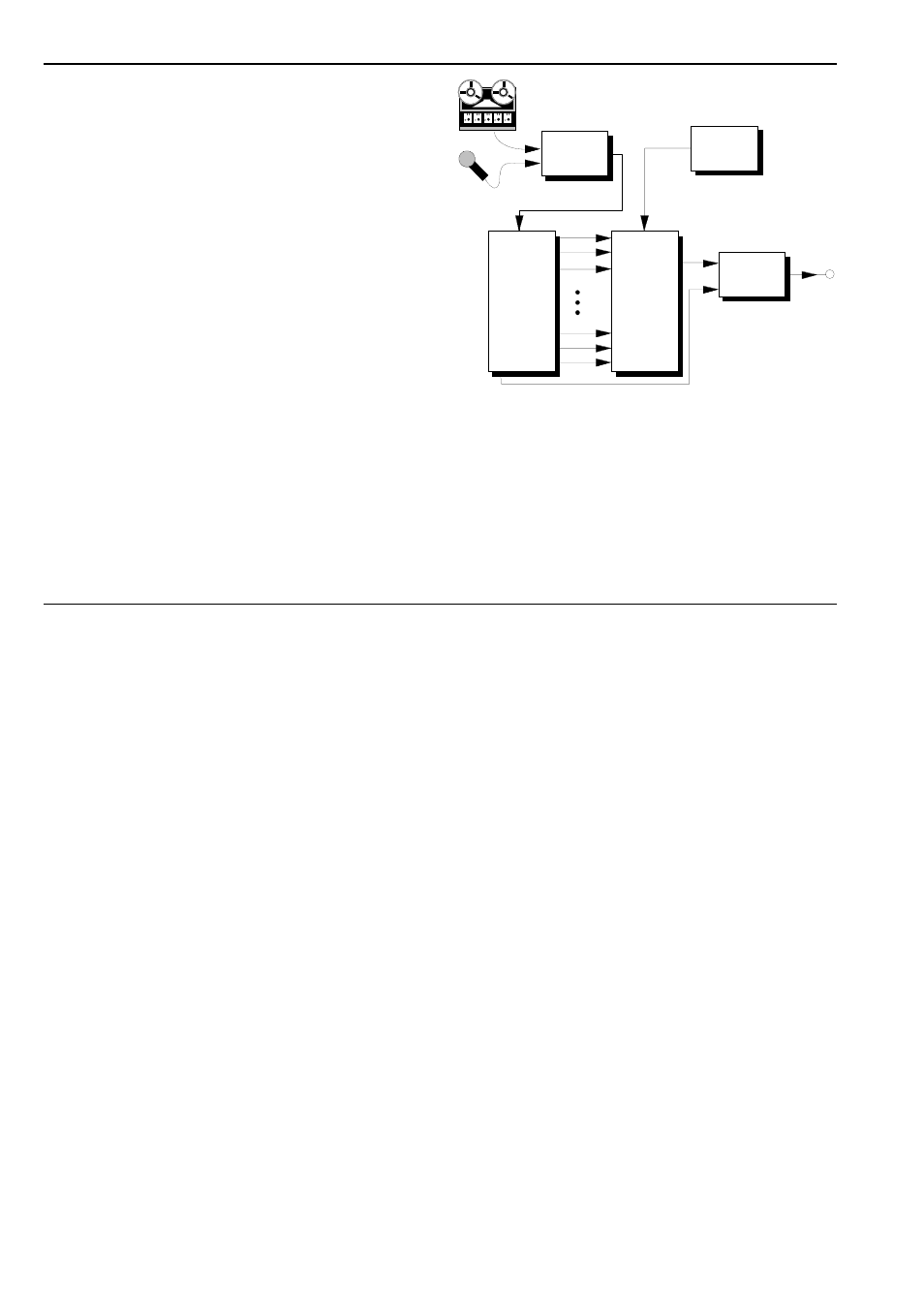
Using just the basic modules
Just with the A-129 /1 and A-129 /2 modules (and an
A-119 external input), all the common vocoder effects
can be produced (see Fig. 2).
D
First patch all the CV outputs on the analysis
section to their respective CV inputs on the synthe-
sis section (band 1 to 1, 2 to 2, and so on)
D
Use an A-119 (External Input) to patch an audio
signal (see above, chapter 5, Basic Principles) into
the speech input socket of the analysis section at
normal A-100 operating level.
D
Experiment with different audio signals for the car-
rier frequency (instrument input), for instance:-
• different overtone-rich waveforms from a VCO,
• pink or coloured noise from an A-118,
• digital noise from an A-117,
• ring modulator outputs,
• two VCOs modulated in the audio range by FM
or AM.
D
Swap the connections between analysis and syn-
thesis sections (see above).
Fig. 2: Basic vocoder schematic
"Frequency displacement"
If instead of patching the outputs from the analysis
section to their ‘proper’ respective inputs in the synthe-
sis section, you swap them about instead, interesting
frequency displacements occur in the vocoder output.
Fig. 3 shows some simple variations; experiment
withall sorts of other possibilities.
A-119
LP
BP 1
BP 2
BP 12
BP 13
HP
LP
BP 1
BP 2
BP 12
BP 13
HP
A-129 /1
A-129 /2
A-138
Audio *
High
Out
Speech
In
Instrum.
In
Voc.
Out
* : VCO
Noise
Dig. Noise
Ring Mod.
AM
FM
...