System a - 100, A-148, Indicators – Doepfer A-100(~ 40 MB) User Manual
Page 453: Doepfer
doepfer
System A - 100
Dual S&H
A-148
3
3. Indicators
1
LEDs
These LEDs give a visual indication of the voltage
level of the sampled and held signal (- LED: negative
voltages, + LED: positive voltages).
4. In / Outputs
!
Trig In
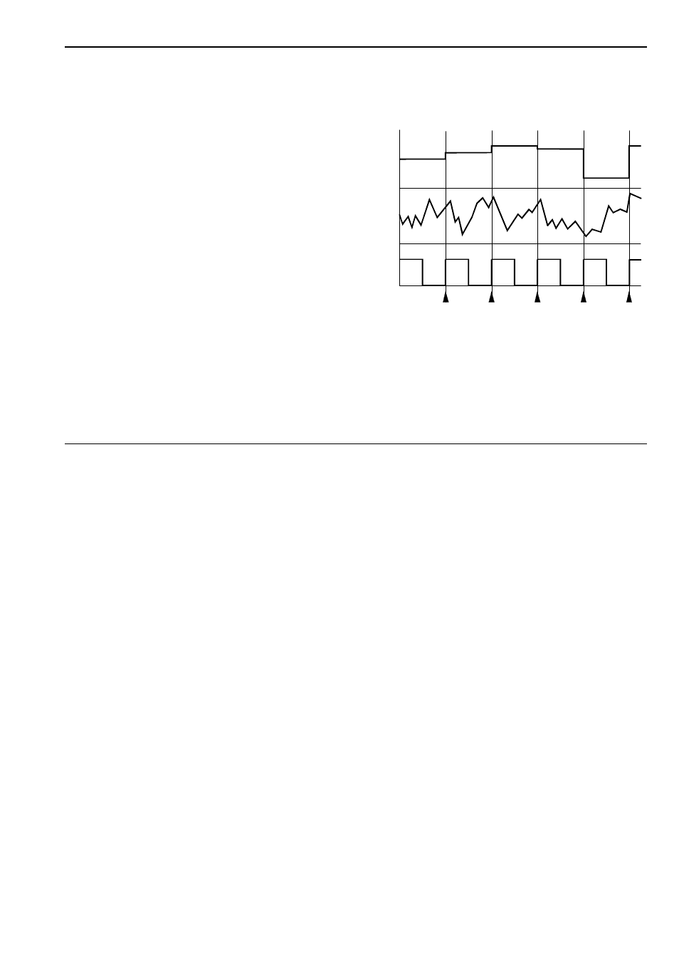
The trigger input signal decides the rate at which the
sampling takes place. Triggering takes place at the
leading edge of the waveform (see arrows in Fig. 1),
so the width of the pulse isn’t important.
"
Smp. In
Socket " is the sample input, where the signal to be
sampled is patched in. The signal fed into this socket
has to be in the range -8V...+8V. For voltages beyond
this range the S&H function will not work any longer.
But the module cannot be destroyed as long as the
voltage is in the range -12V...+12V. And that is the
maximum voltage output from any A-100 module.
Consequently within the A-100 no damage is possible.
§
S&H Out
The ‘sampled and held’ voltage is available at the S&H
output (see Fig. 1).
Fig. 1: S&H module signal diagram
Trig.
In
Smp.
In
S&H
Out
- DIY Synth do-it-yourself analog synthesizer (24 pages)
- MKE Universal Midi Keyboard Electronics Kit (17 pages)
- CTM64 Contact to Midi Interface (main board) (20 pages)
- CTM64 Relay Board (8 pages)
- MTC64 Midi to Gate Interface (main board) (16 pages)
- MTC64 Relay Board (8 pages)
- MTC64 Output Board (transistor driver board) (4 pages)
- MTC64 Power Board (8 pages)
- Pocket Electronic (32 pages)
- Dial Electronic (12 pages)
- Wheel Electronic (16 pages)
- USB64 Universal Midi and USB Controller Electronics Kit (20 pages)
- MBP25 Midi Bass Pedal Electronics Kit (16 pages)
- MTV16 Midi-to-Voltage Interface with 16 Analog Voltage Outputs (8 pages)
- A-100 (8 pages)
- A-100AD5 +5V low cost adapter (46 pages)
- A-100CGK CV/Gate keyboard (12 pages)
- A-101-1 Vactrol Steiner Filter (6 pages)
- A-101-2 Vactrol Lowpass Gate (6 pages)
- A-101-3 Vactrol Modular Phase Filter (10 pages)
- A-101-9 Universal Vactrol Module (14 pages)
- A-102 Diode Low Pass (6 pages)
- A-104 four-fold Trautonium Formant Filter (6 pages)
- A-105 24dB SSM Low Pass (8 pages)
- A-106-1 Xtreme Lowpass/Highpass Filter (12 pages)
- A-107 Multitype Morphing Filter (18 pages)
- A-108 6/12/24/48 Formant Filter (10 pages)
- A-109 Voltage Controlled Audio Signal Processor (10 pages)
- A-110 Standard VCO (12 pages)
- A-111-1 High End VCO (14 pages)
- A-111-5 Synthesizer Voice (22 pages)
- A-112 Sampler/Wavetable Oscillator (24 pages)
- A-113 Subharmonic Oscillator (14 pages)
- A-114 Dual Ringmodulator (6 pages)
- A-115 Audio Divider (6 pages)
- A-116 VC Waveform Processor (6 pages)
- A-117 Digital Noise / 808 Source (8 pages)
- A-118 Noise/Random (6 pages)
- A-119 External Input/Envelope Follower (8 pages)
- A-120 24dB Low Pass 1 (8 pages)
- A-121 12dB Multimode VCF (10 pages)
- A-123 24dB High Pass (no longer available) (8 pages)
- A-124 Wasp Filter (8 pages)
- A-125 VC Phaser (8 pages)