A-175, System a - 100, User examples – Doepfer A-100(~ 40 MB) User Manual
Page 596
A-175
Dual Voltage Inverter
System A - 100
doepfer
4
5. User examples
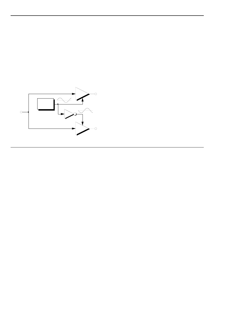
Panning
Fig. 1 shows a typical patch to create Panning - the
shifting of a sound’s position in the stereo picture.
The input signal is simultaneously sent to two linear
VCAs, whose outputs are sent one to the left (Out
L
)
and one to the right (Out
R
) stereo channel. Both VCAs
are being modulated by the same slow LFO. One of
the VCAs has the LFO voltage patched straight into it,
but the other has an A-175 patched in line first, so
receives the LFO voltage inverted.
Fig. 1: Panning
The changing state of the LFO voltages results in
corresponding changes in the perceived position of the
sound in the stereo picture.
H
It’s important to set the gain parameter on
both VCAs to roughly halfway.
P
Interesting types of panning can result if you
use a different modulator (for instance, AM,
FM, Random Voltage, S&H).
If you replace the two VCAs with two A-125
VCPs, the result is a sort of rotating stereo
phasing.
Mirroring a scale or arpeggio
The patch in Fig. 2 shows a way of using two VCOs to
create a mirror-image of a series of notes.
The pitch CV is patched directly to VCO 1, but goes
through an A-175 and is inverted before it gets to VCO
2.
H
The relative pitch of VCO 2 can be controlled
with an attenuator.
LFO
A-130
A-130
A-175
Signal
In
Out
L
Out
R