A-156, System a - 100, Doepfer – Doepfer A-100(~ 40 MB) User Manual
Page 524
A-156
Quantizer
System A - 100
doepfer
6
5. In / Outputs
!
CV In • % CV In
Socket ! and % are the
inputs for the quantizers 1
and 2 respectively. The control voltage to be quantized
is patched into these sockets.
"
CV Out • & CV Out
At
outputs " and & the quantized voltages appear.
§
Trig. In • / Trig. In
If a trigger signal is applied to the
trigger input § or /
the quantization process takes place during
low/high
transition of the trigger signal. If this is not desired
leave the socket un-connected. Quantization then ta-
kes place at the internal rate of about 500Hz.
The external trigger signals are scanned with a rate of
about 1kHz. Therefore the external trigger frequency
has to be less than 500Hz to avoid aliasing effects. In
practice this will be no restriction as normal quantiza-
tion rates are much lower (usually only a few Hz).
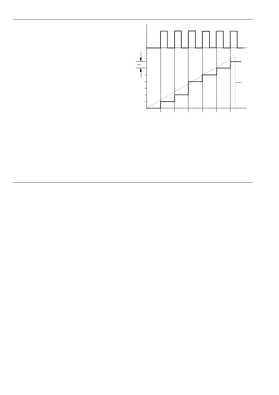
fig. 6: External triggered quantization
1
12
V
Trig.
In
CV
Out
CV
In
- DIY Synth do-it-yourself analog synthesizer (24 pages)
- MKE Universal Midi Keyboard Electronics Kit (17 pages)
- CTM64 Contact to Midi Interface (main board) (20 pages)
- CTM64 Relay Board (8 pages)
- MTC64 Midi to Gate Interface (main board) (16 pages)
- MTC64 Relay Board (8 pages)
- MTC64 Output Board (transistor driver board) (4 pages)
- MTC64 Power Board (8 pages)
- Pocket Electronic (32 pages)
- Dial Electronic (12 pages)
- Wheel Electronic (16 pages)
- USB64 Universal Midi and USB Controller Electronics Kit (20 pages)
- MBP25 Midi Bass Pedal Electronics Kit (16 pages)
- MTV16 Midi-to-Voltage Interface with 16 Analog Voltage Outputs (8 pages)
- A-100 (8 pages)
- A-100AD5 +5V low cost adapter (46 pages)
- A-100CGK CV/Gate keyboard (12 pages)
- A-101-1 Vactrol Steiner Filter (6 pages)
- A-101-2 Vactrol Lowpass Gate (6 pages)
- A-101-3 Vactrol Modular Phase Filter (10 pages)
- A-101-9 Universal Vactrol Module (14 pages)
- A-102 Diode Low Pass (6 pages)
- A-104 four-fold Trautonium Formant Filter (6 pages)
- A-105 24dB SSM Low Pass (8 pages)
- A-106-1 Xtreme Lowpass/Highpass Filter (12 pages)
- A-107 Multitype Morphing Filter (18 pages)
- A-108 6/12/24/48 Formant Filter (10 pages)
- A-109 Voltage Controlled Audio Signal Processor (10 pages)
- A-110 Standard VCO (12 pages)
- A-111-1 High End VCO (14 pages)
- A-111-5 Synthesizer Voice (22 pages)
- A-112 Sampler/Wavetable Oscillator (24 pages)
- A-113 Subharmonic Oscillator (14 pages)
- A-114 Dual Ringmodulator (6 pages)
- A-115 Audio Divider (6 pages)
- A-116 VC Waveform Processor (6 pages)
- A-117 Digital Noise / 808 Source (8 pages)
- A-118 Noise/Random (6 pages)
- A-119 External Input/Envelope Follower (8 pages)
- A-120 24dB Low Pass 1 (8 pages)
- A-121 12dB Multimode VCF (10 pages)
- A-123 24dB High Pass (no longer available) (8 pages)
- A-124 Wasp Filter (8 pages)
- A-125 VC Phaser (8 pages)