System a - 100 9. appendix, Doepfer – Doepfer A-100(~ 40 MB) User Manual
Page 39
doepfer
System A - 100
9. Appendix
31
A
The
yellow/green wire is the safety (earth)
connection, and must be never replaced by
a different colour.
If you’ve been using the AD5 low-cost 5V adaptor, but
are now installing an NT5, you must
remove the AD5
before commissioning the NT5!
9.2 Installing the AD5 low-cost 5V adaptor
The
AD5 can be used for the 5V power supply, as long
as the following applies:
•
The current for the modules that require a 5V
supply doesn’t exceed 100 mA (e.g. only one A-113
or one A-190-1 or one A-191)
•
There is enough current handling still available on
the +12V supply to cope with the current require-
ments of the 5V modules.
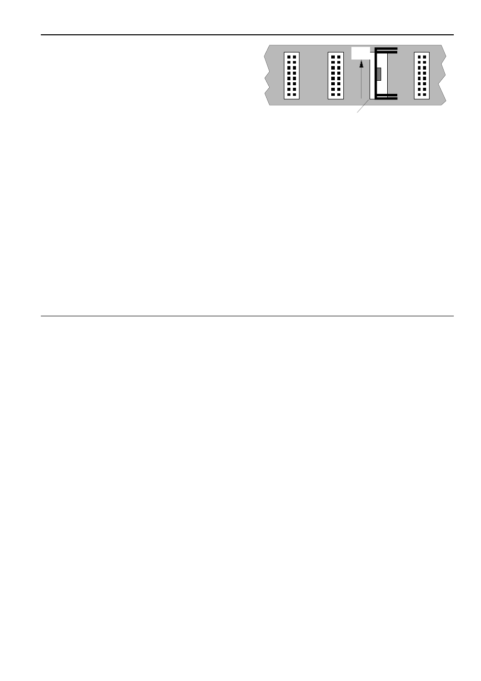
The AD5 adaptor can be connected to any available
16-way socket on the system bus board (see Fig. 11).
This will feed +5V to modules on that bus, as long as
their current requirements don’t exceed 100mA.
Fig. 11: Connecting the 5V low-cost adaptor
(1: system bus board, 2: AD5, 3: heat sink)
To install the AD5, do the following:
Isolate the A-100 rack from the mains power sup-
ply by removing the main plug.
D Carefully insert the AD5 into a free socket on the
bus board.
A
Make sure that the AD5 is the right way up,
and aligned correctly with the bus socket.
The correct position is shown on a sticker
(with the
arrow pointing upwards, and the
red mark at the bottom - see Fig. 11).
rote Markierung
oben
➀
➁
➂
red mark
up