A-156, System a - 100, Controls – Doepfer A-100(~ 40 MB) User Manual
Page 522: Doepfer
A-156
Quantizer
System A - 100
doepfer
4
4. Controls
1
Switch
The
3-position switch 1 determines the scale type.
In position "
All" a chromatic scale (see fig. 2) is used,
i.e. the voltage step is 1/12 V.
H
In this case switches 2 and 3 have no function.
fig. 2: chromatic scale (semitone grid)
In the "
Major" position major chords or major scales
are generated depending upon the position of switch
2.
In the "
Minor" position minor chords or minor scales
are generated depending upon the position of switch
2.
2
Switch
The
3-position switch 2 determines the output
mode.
In the "
Scale" position all voltages corresponding to
the scale selected with switch 1 (major or minor) are
passed to the control voltage output (see fig. 3).
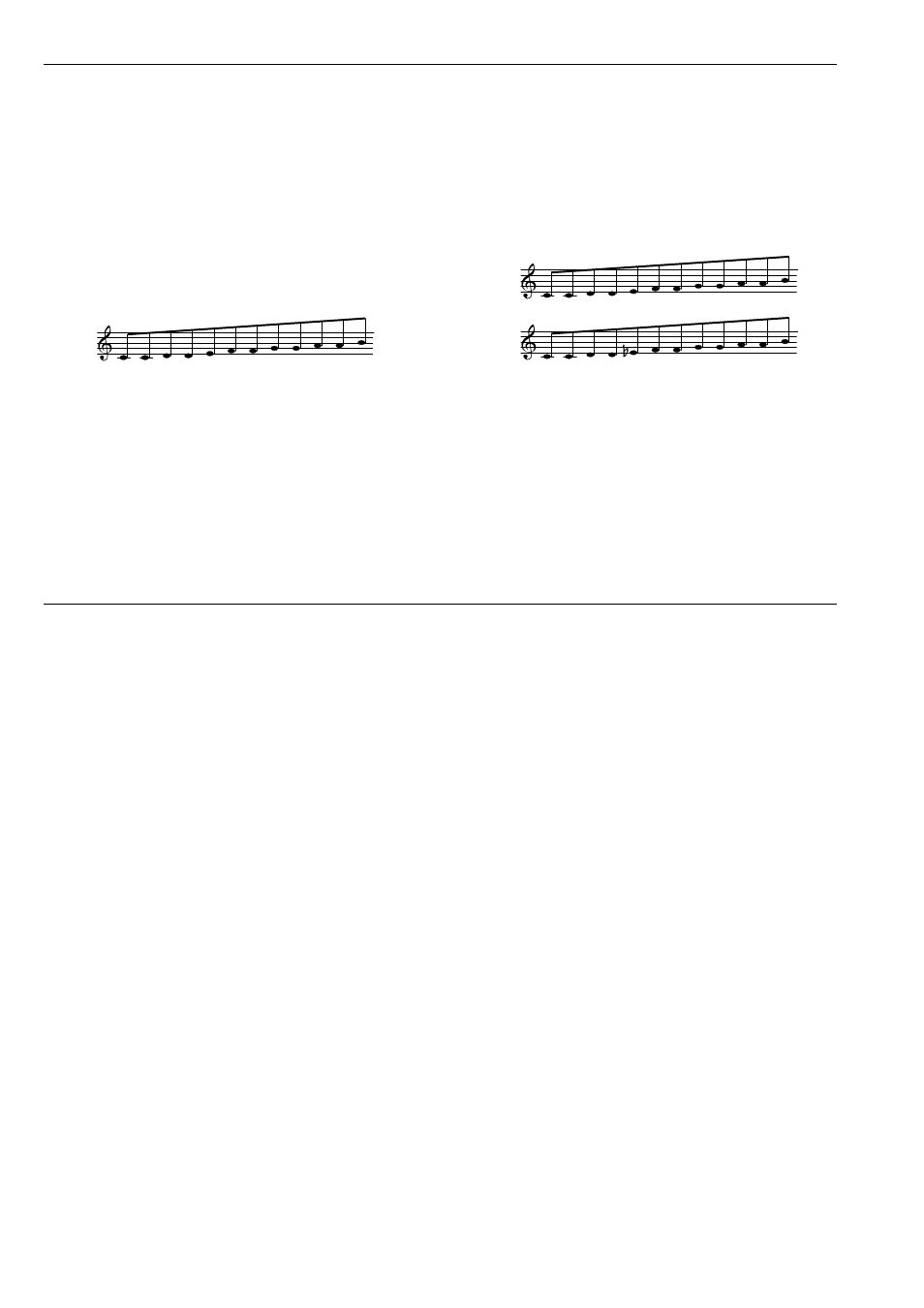
fig. 3: Major scale (a) and minor scale (b)
H
During scanning of the control voltage all 12
steps of an octave are generated. Therefore
some steps appear twice in the graph above.
The same is valid for all other grids too.
In the "
Chord" position only voltages corresponding to
the chord type selected with switch 1 (major or minor)
are passed to the control voltage output (see fig. 4
a+b).
#
#
#
#
#
a
b