System a - 100, A-172, Basic principles – Doepfer A-100(~ 40 MB) User Manual
Page 585: Controls
doepfer
System A - 100
MAX / MIN
A-172
3
3. Basic principles
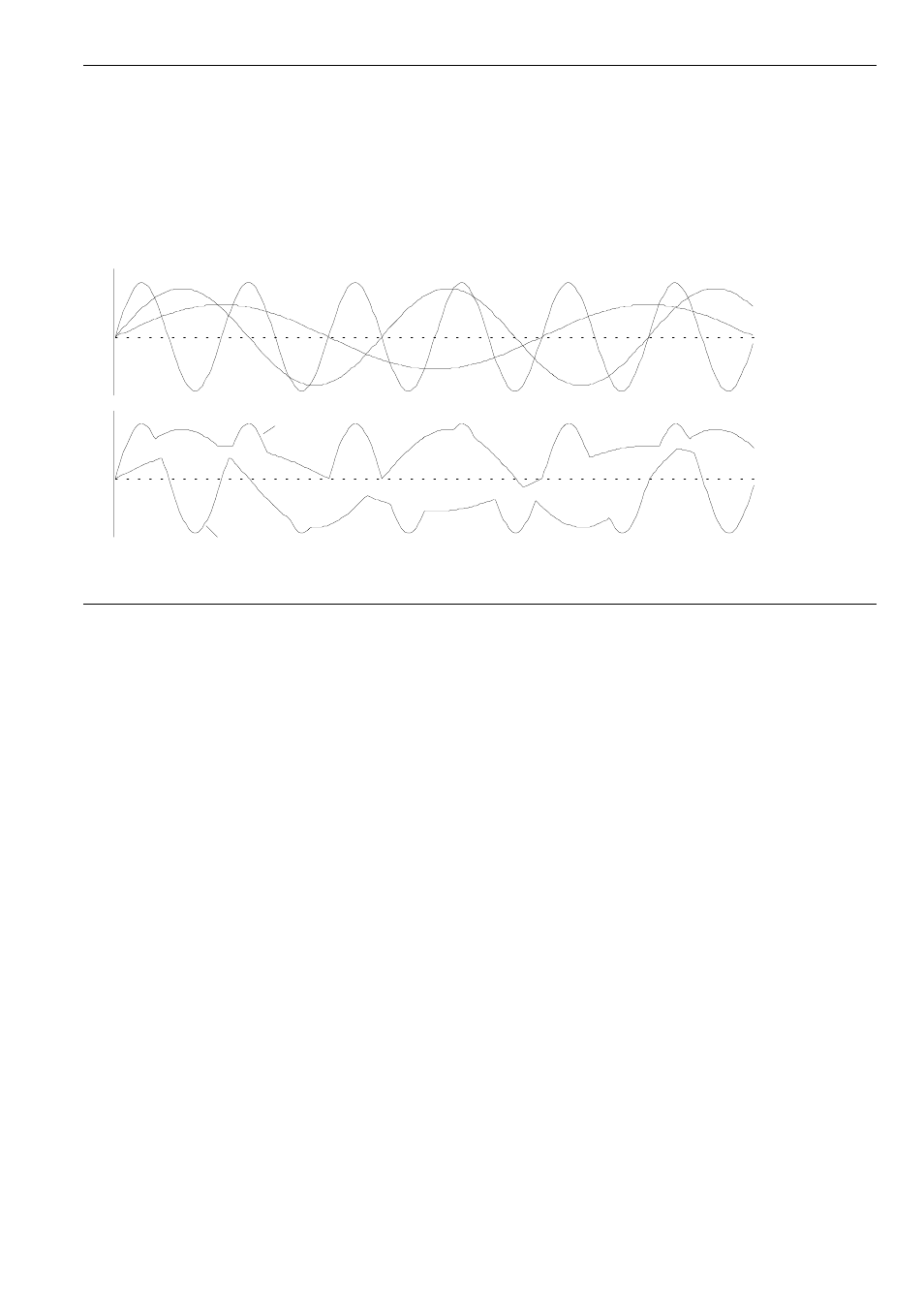
The module permanently picks the maximum resp.
minimum voltage out of the four analog input signals
and outputs these voltages to the maximum resp.
minimum jack socket. Fig. 1 shows the working princi-
ple by means of three sine waves with different fre-
quencies and levels. The upper section shows three
input signals , the lower section shows the correspon-
ding outputs.
Fig. 1: Maximum/Minimum module - how it works
4. Controls
1
Max. Ctr. • 2 Min. Ctr.
These LEDs display the positive resp. negative part of
the output signals at the Maximum % resp. Minimum
output &.
In
Out
Min. Out
Max. Out
See also other documents in the category Doepfer Audio:
- DIY Synth do-it-yourself analog synthesizer (24 pages)
- MKE Universal Midi Keyboard Electronics Kit (17 pages)
- CTM64 Contact to Midi Interface (main board) (20 pages)
- CTM64 Relay Board (8 pages)
- MTC64 Midi to Gate Interface (main board) (16 pages)
- MTC64 Relay Board (8 pages)
- MTC64 Output Board (transistor driver board) (4 pages)
- MTC64 Power Board (8 pages)
- Pocket Electronic (32 pages)
- Dial Electronic (12 pages)
- Wheel Electronic (16 pages)
- USB64 Universal Midi and USB Controller Electronics Kit (20 pages)
- MBP25 Midi Bass Pedal Electronics Kit (16 pages)
- MTV16 Midi-to-Voltage Interface with 16 Analog Voltage Outputs (8 pages)
- A-100 (8 pages)
- A-100AD5 +5V low cost adapter (46 pages)
- A-100CGK CV/Gate keyboard (12 pages)
- A-101-1 Vactrol Steiner Filter (6 pages)
- A-101-2 Vactrol Lowpass Gate (6 pages)
- A-101-3 Vactrol Modular Phase Filter (10 pages)
- A-101-9 Universal Vactrol Module (14 pages)
- A-102 Diode Low Pass (6 pages)
- A-104 four-fold Trautonium Formant Filter (6 pages)
- A-105 24dB SSM Low Pass (8 pages)
- A-106-1 Xtreme Lowpass/Highpass Filter (12 pages)
- A-107 Multitype Morphing Filter (18 pages)
- A-108 6/12/24/48 Formant Filter (10 pages)
- A-109 Voltage Controlled Audio Signal Processor (10 pages)
- A-110 Standard VCO (12 pages)
- A-111-1 High End VCO (14 pages)
- A-111-5 Synthesizer Voice (22 pages)
- A-112 Sampler/Wavetable Oscillator (24 pages)
- A-113 Subharmonic Oscillator (14 pages)
- A-114 Dual Ringmodulator (6 pages)
- A-115 Audio Divider (6 pages)
- A-116 VC Waveform Processor (6 pages)
- A-117 Digital Noise / 808 Source (8 pages)
- A-118 Noise/Random (6 pages)
- A-119 External Input/Envelope Follower (8 pages)
- A-120 24dB Low Pass 1 (8 pages)
- A-121 12dB Multimode VCF (10 pages)
- A-123 24dB High Pass (no longer available) (8 pages)
- A-124 Wasp Filter (8 pages)
- A-125 VC Phaser (8 pages)