System a - 100, A-115, Controls – Doepfer A-100(~ 40 MB) User Manual
Page 235: User examples, Doepfer
doepfer
System A - 100
DIVIDER
A-115
3
3. Controls
1
Orig.
This attenuator controls the amount of the original
input signal present in the mix output.
2
F / 2 ... 5 F / 16
These attenuators 2 to 5 control the amount of the
respective sub-octaves present in the mix output.
Say your production needs a stronger bass-line: you
can add a square wave an octave below the original
signal simply by setting attenuators 1 and 2 to maxi-
mum, and attenuators 3 to 5 to 0.
4. In / Outputs
!
Audio In
Socket ! is the divider’s input. Connect up the signal
whose frequency you wish to divide.
H
The divider is basically set up to divide rectangle
waveforms. If you put another waveform into the
input (for instance a sawtooth) the A-115 will
change it into a square wave before dividing it.
"
Audio Out
At output " the total mix of the original signal and four
sub-octaves (depending on the position of attenuators
1
to 5) is available.
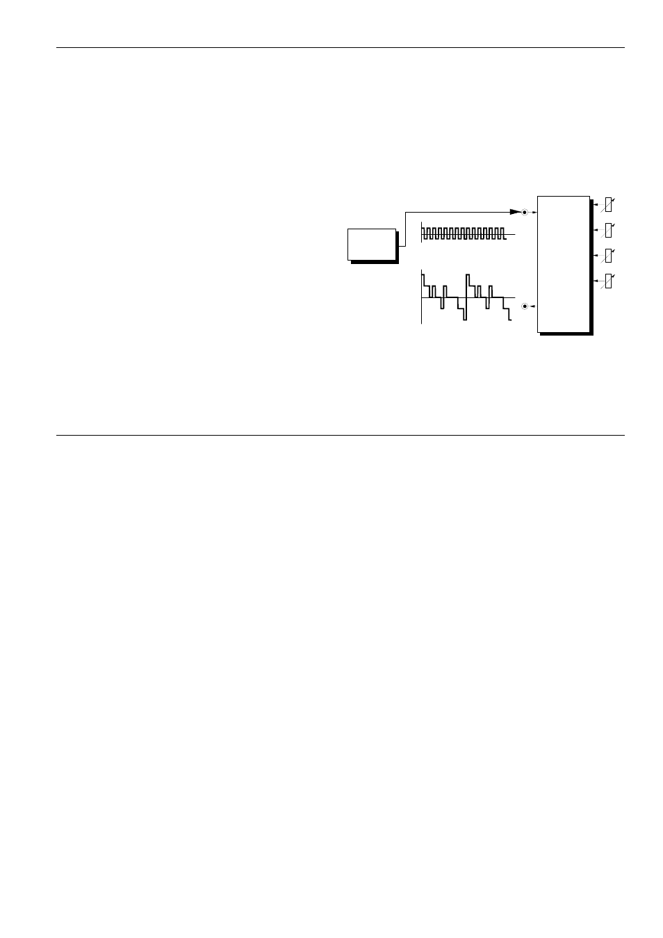
5. User examples
A-115 as a "frequency generator"
With the A-115, you can start out with a VCO’s basic
square wave and produce more complex waveforms.
Fig. 1 shows how the A-115 can take a simple square
wave and create a new wave form. Turn attenuators
1
to 4 up to maximum, and set attenuator 5 to 0.
Fig. 1: The A-115 as a frequency generator
Experiment with different level settings for each at-
tenuator, and also with other waveforms (for instance,
a square wave modulated by a slow LFO).
Audio In
F / 2
Audio
Out
F / 8
A-115
DIVIDER
F / 4
In
VCO