A-129 /5, System a - 100, User examples – Doepfer A-100(~ 40 MB) User Manual
Page 338: Doepfer
A-129 /5
Voiced/Unvoiced Detector
System A - 100
doepfer
4
$
Unvoiced Input
This unvoiced carrier signal input $ is used to patch
in the sound source you wish to use for the carrier
signal for unvoiced sounds.
As a rule, you’d tend to use the output from a noise
module (A-117, A-118), a high-frequency sawtooth
wave, or the 6 Oscillator output from an A-117 mo-
dule.
%
Voiced Input
This voiced carrier signal input % is used to patch in
the sound source you wish to use for the carrier
signal for voiced sounds.
Usually, you’d tend to find a low-mid frequency VCO or
mix of several VCOs doing this job.
&
Voiced / Unvoiced Output
Depending on the status of the voiced/unvoiced detec-
tor switching, output & relays the input signal from
socket $ or %.
5. User examples
Vocoder block diagram including A-129 /5
The way the A-129/5 should be patched into the whole
vocoder system is shown in fig. 2 (see next page).
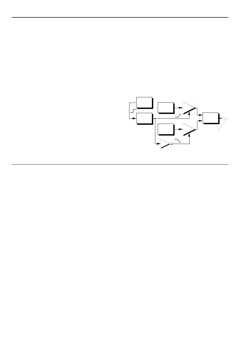
Smoothing Voiced / Unvoiced transitions
Whereas the A-129/5’s internal switch produces an
abrupt change from voiced to unvoiced carrier and
vice versa, it’s possible to patch the gate output to a
slew limiter, invert one of the carrier VCAs, and pro-
duce a smooth transition.
fig. 1: smoothing the change of carrier signals
Gate Out
A-175
A-129 /5
A-138
A-117
A-118
to
Speech Input
of A-129 /1
A-170
A-110
A-111
A-130
A-130