System a - 100, User examples, Doepfer – Doepfer A-100(~ 40 MB) User Manual
Page 485
doepfer
System A - 100
Voltage Addressed T&H/Switch A-152
7
5. User Examples
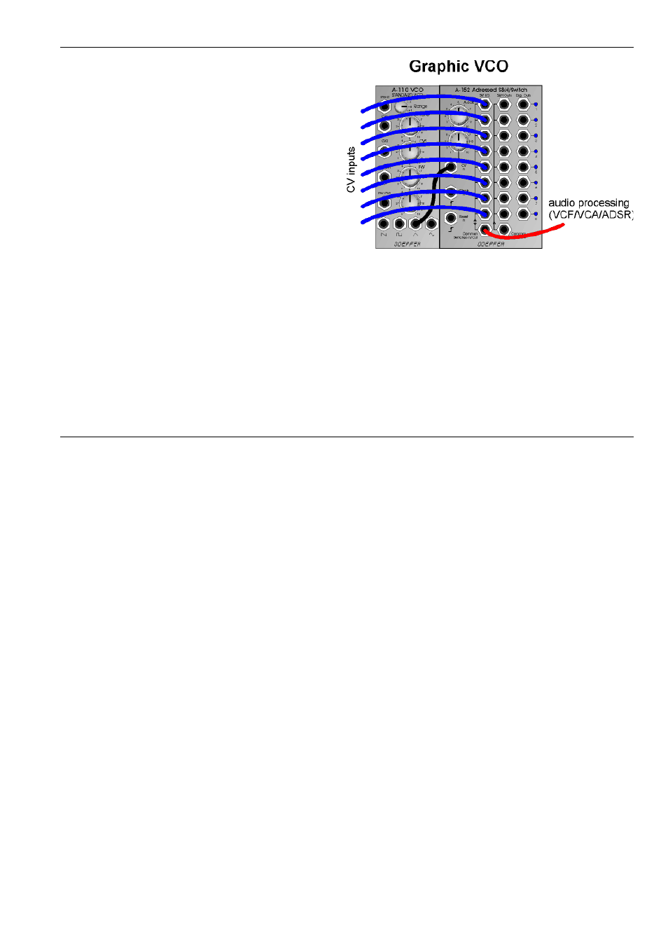
Graphic VCO
The right picture shows the principle patch for a so-
called graphic VCO. For a graphic VCO the waveform is
determined by a sequence of voltage levels. Normally
the levels are adjusted with faders and the fader positi-
ons represent the waveform. In the A-100 such a VCO is
not available as we believe that the expenditure and
costs do not correspond to the result. From our point of
view the features of a graphic VCO are overestimated
very often. But with the A-152 one has the tool to built a
graphic VCO with a few additional modules only. And
that's how it works:
The CV address input of the A-152 is connected to the
output of a VCO (e.g. sawtooth or triangle output of an
A-110 or A-111). The manual address control and the
CV attenuator are adjusted so that just all 8 LEDs of the
A-152 light up, i.e. that all 8 stages of the A-152 are
addressed while the VCO passes through it's waveform
(this is why only sawtooth/triangle/sine are suitable wa-
veforms but not rectangle). The CV controlled address
generator of the A-152 is able to work up to moderate
audio frequencies. If different voltages are applied to the
eight multiplexer inputs of the A-152 one obtains a
graphic VCO signal at the common multiplexer output
that has the same frequency as the VCO.
Here are some examples how to generate the eight
voltages:
• 8 fixed voltages (e.g. from the CV source module
A-176): This is the "classic" graphic VCO with manu-
ally adjustable values (for DIY's: 8 faders connected
between GND and +12V could be used too)
• 8 automatically varying voltages (e.g. 8 LFO outputs
from two A-143-3)
• 8 random analog voltages (e.g. random voltages
from A-118 or A-149-1 or S&H A-148)
• 8 random digital voltages (e.g. A-149-2)
• or any combination of the above suggestions