System a - 100, User examples, Doepfer – Doepfer A-100(~ 40 MB) User Manual
Page 345: Typical voltage controlled amplification, Amplitude modulation
doepfer
System A - 100
VCA
A-130 / A-131
5
5. User examples
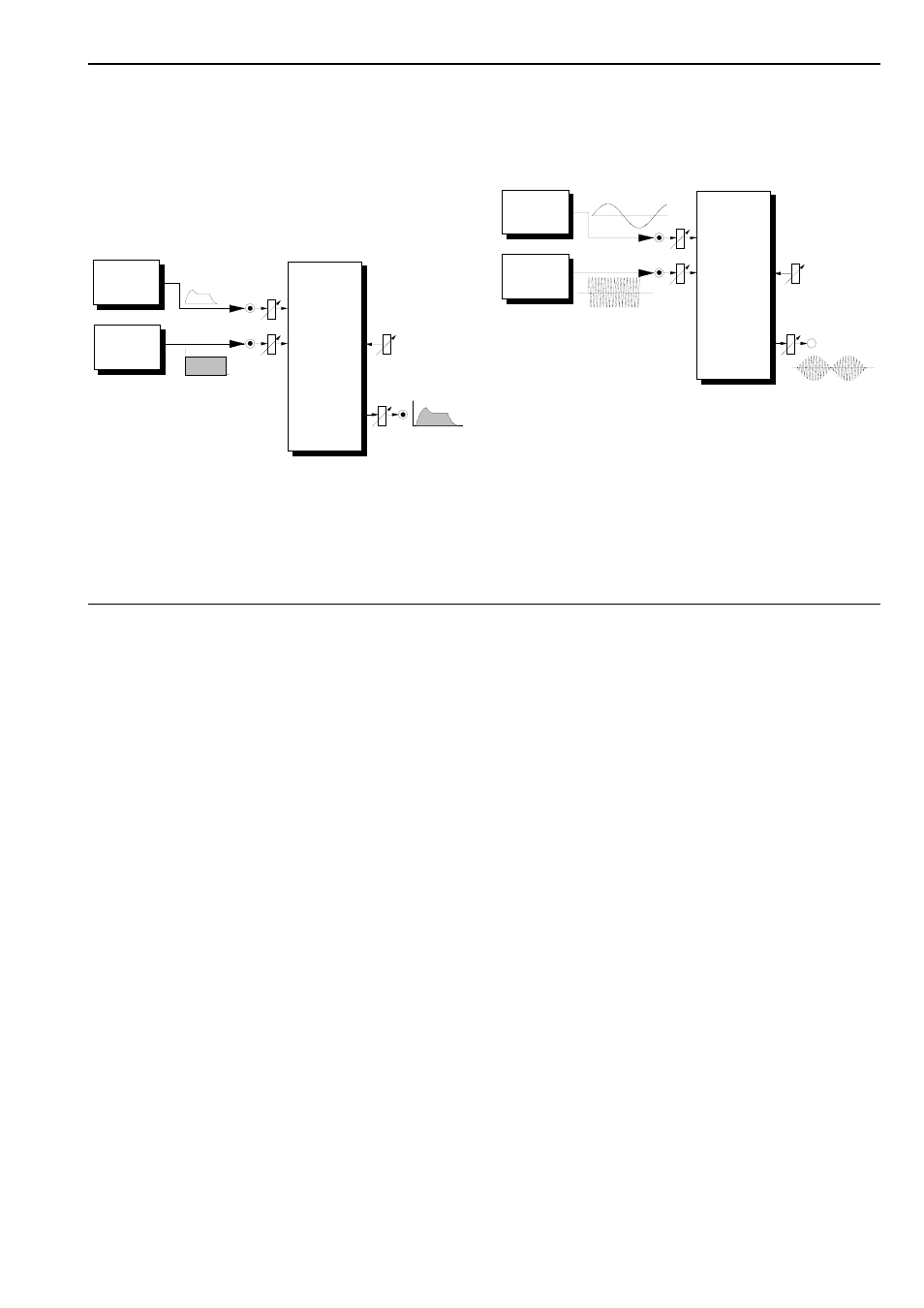
Typical voltage controlled amplification
A standard VCA patch is shown in Fig. 4. An ADSR
envelope produces a time-dependent amplification
curve, which can affect any sound source you choose.
The curve can be very quick (with a fast envelope) or
it can produce long, slow changes in the volume of a
sound.
Fig. 4: Time dependent amplification using an ADSR
Amplitude modulation
In Fig. 5, an LFO is modulating an A-130 linear VCA
(with Gain > 0), so that the amplification changes
cyclically with the LFO’s voltage (Amplitude modula-
tion/AM.) With an LFO frequency in the sub-audio
range (1 Hz to around 15 Hz) the result is Tremolo
(Fig. 5). With a modulation frequency in the audio
range, sidebands occur like those produced by FM
(Frequency Modulation), and interesting timbres
emerge.
Fig. 5: VCA amplitude modulation with an LFO
Modulation depth is adjusted with control 2.
Fig. 6 shows a way of voltage-controlling this modula-
tion depth using another VCA. In this example, the
VCAs have the following functions:
• VCA 1 (A-130): AM control
• VCA 2 (A-131): total volume control
• VCA 3 (A-130): modulation depth control
NOISE
ADSR
Audio
In 1
CV 2
CV 2
Gain
A-131
VCA-EXP.
In 1
Audio Out
Out
LFO
VCO
Audio
In 1
CV 2
CV 2
Gain
A-130
VCA-LIN.
In 1
Audio Out
Out
Gain > 0