Appendix system a - 100, Doepfer – Doepfer A-100(~ 40 MB) User Manual
Page 44
9. Appendix
System A - 100
doepfer
36
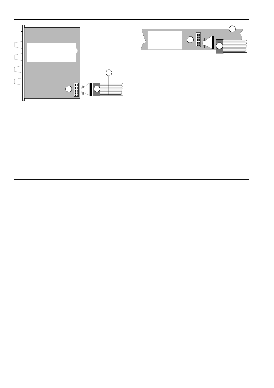
Fig. 1:
Connecting the ribbon cable to the module
D Now join the free end of the ribbon cable (see
2
in
Fig. 2) to the nearest available position on the
system bus board (see
1
in Fig. 2).
A
Again ensure that
the coloured marking on
the ribbon cable is at the
bottom of the
module’s connector (see
3
in Fig. 1) and
that the connection is perfect, and
pushed
fully home, not at a slight angle. Failure to
check this may again result in disaster.
Fig. 2:
Connecting the ribbon cable to the bus
board.
D Now fix the module solidly in its case.
D Re-connect the A-100 MNT’s power supply, and
then switch on the mains again.
D Test out the newly installed module.
If it doesn’t seem to be working as expected,
imme-
diately disconnect the system from the power sup-
ply again.
In this case, double-check the connections, making
completely sure that the ribbon cable is the right
way round where it connects to the module and to
the bus.
Best ückungsseite
1
3
2
3
2
1
Busplatine
components side
bus board
- DIY Synth do-it-yourself analog synthesizer (24 pages)
- MKE Universal Midi Keyboard Electronics Kit (17 pages)
- CTM64 Contact to Midi Interface (main board) (20 pages)
- CTM64 Relay Board (8 pages)
- MTC64 Midi to Gate Interface (main board) (16 pages)
- MTC64 Relay Board (8 pages)
- MTC64 Output Board (transistor driver board) (4 pages)
- MTC64 Power Board (8 pages)
- Pocket Electronic (32 pages)
- Dial Electronic (12 pages)
- Wheel Electronic (16 pages)
- USB64 Universal Midi and USB Controller Electronics Kit (20 pages)
- MBP25 Midi Bass Pedal Electronics Kit (16 pages)
- MTV16 Midi-to-Voltage Interface with 16 Analog Voltage Outputs (8 pages)
- A-100 (8 pages)
- A-100AD5 +5V low cost adapter (46 pages)
- A-100CGK CV/Gate keyboard (12 pages)
- A-101-1 Vactrol Steiner Filter (6 pages)
- A-101-2 Vactrol Lowpass Gate (6 pages)
- A-101-3 Vactrol Modular Phase Filter (10 pages)
- A-101-9 Universal Vactrol Module (14 pages)
- A-102 Diode Low Pass (6 pages)
- A-104 four-fold Trautonium Formant Filter (6 pages)
- A-105 24dB SSM Low Pass (8 pages)
- A-106-1 Xtreme Lowpass/Highpass Filter (12 pages)
- A-107 Multitype Morphing Filter (18 pages)
- A-108 6/12/24/48 Formant Filter (10 pages)
- A-109 Voltage Controlled Audio Signal Processor (10 pages)
- A-110 Standard VCO (12 pages)
- A-111-1 High End VCO (14 pages)
- A-111-5 Synthesizer Voice (22 pages)
- A-112 Sampler/Wavetable Oscillator (24 pages)
- A-113 Subharmonic Oscillator (14 pages)
- A-114 Dual Ringmodulator (6 pages)
- A-115 Audio Divider (6 pages)
- A-116 VC Waveform Processor (6 pages)
- A-117 Digital Noise / 808 Source (8 pages)
- A-118 Noise/Random (6 pages)
- A-119 External Input/Envelope Follower (8 pages)
- A-120 24dB Low Pass 1 (8 pages)
- A-121 12dB Multimode VCF (10 pages)
- A-123 24dB High Pass (no longer available) (8 pages)
- A-124 Wasp Filter (8 pages)
- A-125 VC Phaser (8 pages)