System a - 100, A-174, Controls – Doepfer A-100(~ 40 MB) User Manual
Page 589: Doepfer
doepfer
System A - 100
Joy Stick
A-174
3
3. Controls
1
X Y Joy Stick
With the Joy Stick 1 the control voltages appearing
at the CV outputs ! resp. " are adjusted. The output
voltage range is about 7 V, i.e. about -3.5 V ... +3.5 V
with symmetrical offset adjustment (i.e. 0V in the neu-
tral position).
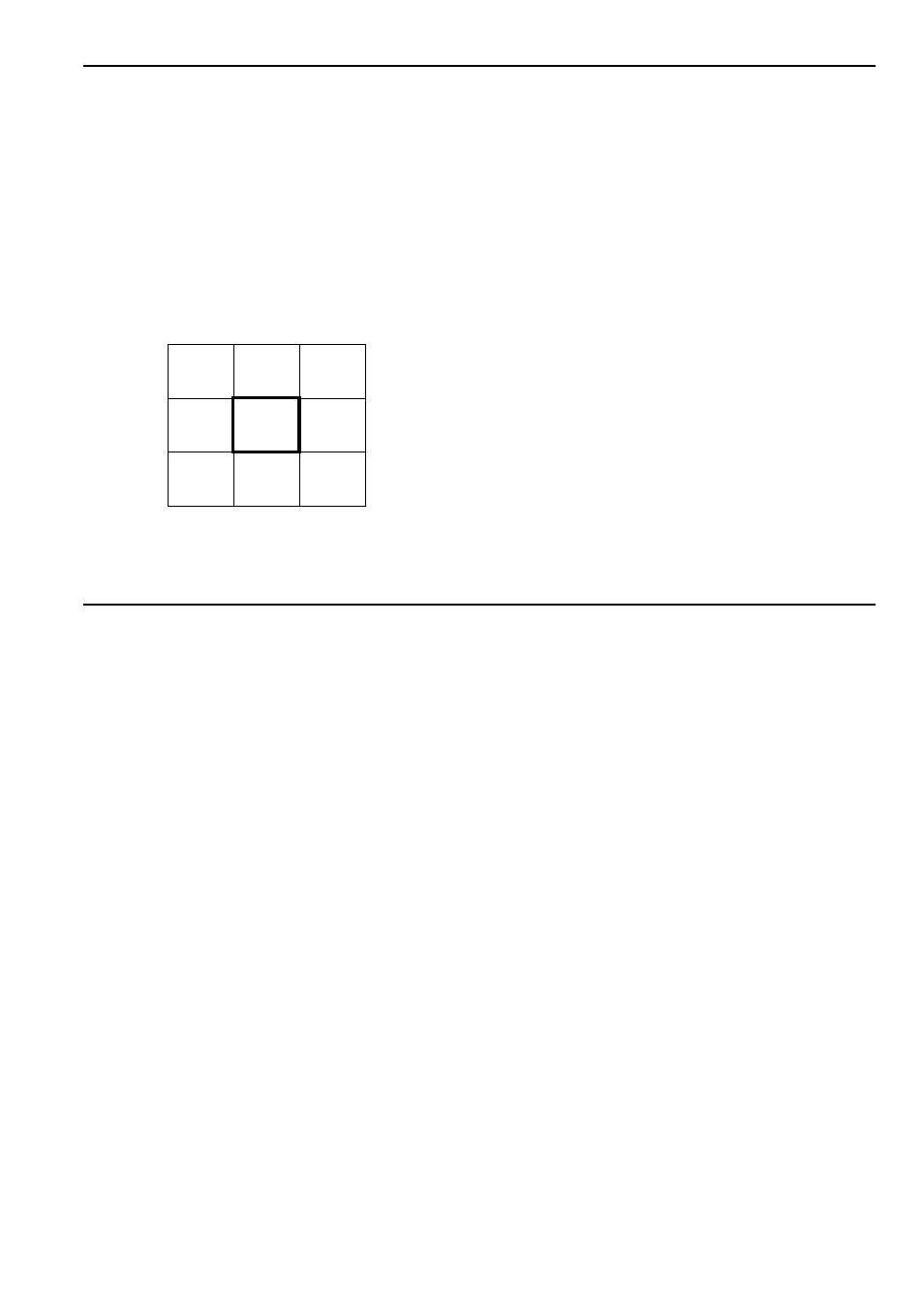
The control voltage CV X is controlled by horizontal,
CV Y by vertical movement of the joy stick lever. The
following assignment applies:
The actual voltages appearing at the CV outputs de-
pend also on the settings of the offset controls 2 resp.
4
.
P
The joy stick used in the A-174 module is
spring-loaded, i.e. the lever returns back to
the neutral position as soon as it is released.
If the spring is removed for one direction the
joy stick is no longer spring-loaded for this
direction. But as the spring is destroyed
when removed this cannot be re-established
! The joy stick is available as spare part
(about US$35.00).
2
Offs. Y • 4 Offs. X
With the offset control 2 resp. 5 the zero point (offset)
is adjusted. If 0V CV output is required in the neutral
position the offset control is adjusted until both LEDs 3
resp. 5 of the direction in question are off. For some
applications a positive offset may be useful (e.g. for
A-132 VCA control).
3
LEDs Y • 5 LEDs X
The LEDs 3 resp. 5 display the present voltages
appearing at the outputs ! resp. ". For both positive
(+) and negative (-) voltages a separate LED is avai-
lable.
X: -3.5
Y: +3.5
X: 0
Y: +3.5
X: +3.5
Y: +3.5
X: -3.5
Y: 0
X: 0
Y: 0
X: +3.5
Y: 0
X: -3.5
Y: -3.5
X: 0
Y: -3.5
X: +3.5
Y: -3.5