Doepfer – Doepfer A-100(~ 40 MB) User Manual
Page 189
DOEPFER
DOEPFER
DOEPFER
DOEPFER
System A-100
Synthesizer Voice A-111-5
21
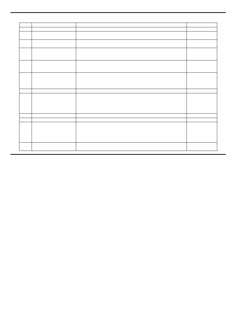
Jumper Overview
Name Function
Explanation
Factory default
JP1
A-100 Bus
Bus connection
bus cable
JP2
CV Bus
Connects the CV line of the A-100 bus to the VCO frequency control
voltage input (in addition to the VCO F socket)
installed
JP3
Gate bus
Connects the Gate line of the A-100 bus to the switching contact of
the ADSR Gate socket
installed
JP4
VCO tune range
Adjusts the range of the VCO tune control:
Installed Æ tune range ~ six octaves
Installed Æ tune range ~ one octave
not installed
(connected to
one pin only)
JP5
Audio Æ Bus/+5V
Connects the audio output to +5V line (!) of the A-100 bus
Can be used only for special applications and if the +5V line of the A-
100 bus board is unused. Otherwised problems will occur.
not installed
JP6
Relation VCO/ext. signal
Adjusts the loudness relation of the internal VCO and the external
audio signal:
installed Æ VCO only
not installed Æ VCO and external signal with same level
installed
(one pin only)
JP7
Inverter input
Connects LFO1 output to the internal inverter
installed
JP8
Inverter output
Connects the output of the internal inverter to the socket LFO1
The factory default is inverted LFO1, the inverter can be used for
other applications too (e.g. inverted ADSR or LFO2 output in
combination with JP9 or JP10, or direct output of LFO1 or LFO2
without inverting)
installed
JP9
ADSR out
Internal ADSR output
- (single pin)
JP10
LFO2 out
Internal LFO2 output
- (single pin)
JP11
VCF tracking source
Selects the CV source for VCF tracking (can be turned on / off / half
by means of the Track switch):
Upper position: VCF tracking controlled by the CV line of the A-100
bus
Lower position: VCF tracking controlled by the VCO F socket
installed
(lower position)
JP12
CV Bus to VCF
Connects the CV line of the A-100 bus to the switching contact the
VCF F socket.
not installed