System a - 100, A-134, Basic layout – Doepfer A-100(~ 40 MB) User Manual
Page 357: Controls and indicators, Doepfer, Voltage controlled panning, 1 leds
doepfer
System A - 100
Voltage Controlled Panning
A-134
3
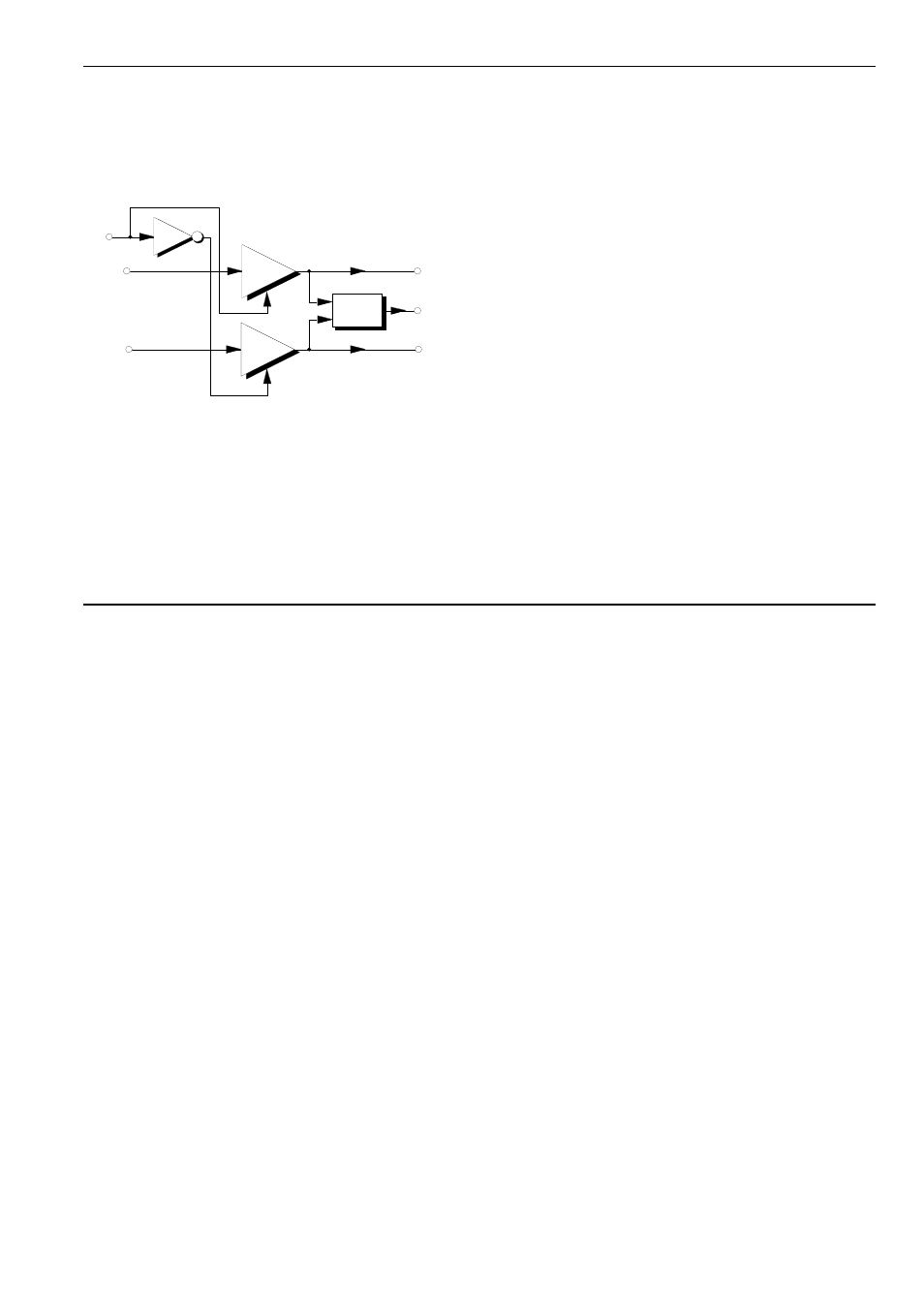
3. Basic layout
The A-134 provides both manual and voltage-
controlled panning. It basically contains two matched
linear VCAs like the A-130, and a mixer (see fig. 1).
Fig. 1: basic construction
In input mixing mode, the signals from the two audio
inputs are mixed and sent to Mix Output &. By using
the two pan controls 2 and/or any control voltages
connected, you can control the relative amounts of
the two input signals in the mix. The matched
VCAs, with one signal inverted, enable the relative le-
vels of the signals to be controlled automatically.
In output panning mode, the signal present at audio
input 1 (§) is sent to the left (%) and right (/) audio
outputs at levels determined by the pan control 2 and/
or the control voltage/s input to the module. In this
way, you can control the position of the signal in the
stereo soundstage.
A typical application is to make a signal move regu-
larly about in the stereo soundstage. To do this, a
slow LFO is connected to CV input ! and/or " on the
A-134.
4. Controls and indicators
1 LEDs
The two LEDs 1 indicate the level of signals going
to outputs %, & and /; how they do this depends on
the mixing / panning mode:
Input mixing mode:
In this mode, the left LED refers to audio input §, and
the right to audio input $. The LEDs show the relative
signal levels from each of the inputs being sent to
Mix output &. Table 1 shows the result of differing
control voltages or positioning of the Pan control.
CV
VCA 1
VCA 2
Mix
Audio
In 1
Audio
In 2
Left
Out
Right
Out
Mix
Out
Inv