Rockwell Automation 7000L PowerFlex Medium Voltage AC Drive (C Frame) - Classic Control User Manual
Page 497
Troubleshooting
7-13
7000 “C” Frame
7000L-UM300I-EN-P – June 2013
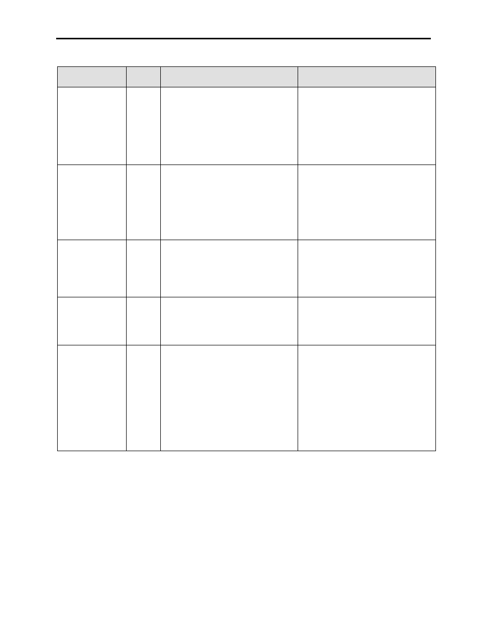
FAULT
MESSAGE
FAULT
CODE
DESCRIPTION
RECOMMENDED ACTIONS
Line Fltr Cap OV
176
The measured line voltage Vline Bridge
(P696) has exceeded Line Overvoltage Trip
(P165) for the duration set in Line
Overvoltage Delay (P166). This is the only
uncompensated voltage, representing the
voltage on the input to the bridge. All other
voltages in the line-side are compensated
using L commutation.
– Verify the parameters are set properly
– Verify VSB connections and tap settings,
resistor values, and grounds
– This is less likely to be caused by a true
Line Overvoltage and more likely to be
due to the effects of capacitive leading
VARs on a high-impedance system
– Tap down the input if possible
Line Harmonic OV
200
The drive has detected a steady-state
resonance-induced overvoltage on the line.
This is defined at the level set in Harmonic
OV Trip (P675) for the delay Harmonic OV
Delay (P676) (on top of normal line voltage)
for 1 second. The drive only detects the 5
th
harmonic to eliminate nuisance faults from
capacitor charging events.
– Verify waveforms show excessive
harmonics using oscilloscope on SCBL
unfiltered voltage testpoints
– Investigate sources for excessive
harmonics on customer power system
– Contact factory for possible re-tuning of
input filter
Line HCS Power
175
The power supplied to the DC Link Hall-
Effect Current Sensor (±24VDC) is
monitored on the control board and will fault
the drive if the voltage is out of tolerance.
– Verify the DC voltage on the DC/DC
supply, at the SCB-L terminals, and at
the Current Sensor
– Check the Current Sensor wiring and
ensure all connections are per the
Electrical Drawing
Line Heartbeat
25
The DCB-M has detected the loss of the
heartbeat signal from the DCB-L
– Verify DC Control voltages to both DCBs
– Possible Failed DCB – Check LED status
of both boards and compare with table in
the manual – Recycle power and replace
board if necessary
Line Neutral OV
192
For SCR rectifiers, the Neutral-to-Ground
voltage calculated from the measured line
voltages has exceeded Ground Fault
Overvoltage Trip (P587) for the duration set
in Ground Fault Overvoltage Delay (P588).
For PWM rectifier, the Neutral-to-Ground
voltage is measured directly from the Line
Filter Capacitor Neutral. In both cases, the
actual value is displayed in V Neutral Line
(P589)
– DESIGNED FOR PWM-Rectifier ONLY:
– Insulation Failure – Megger the motor
insulation/motor cables/drive insulation to
ground
– Verify the integrity of the input grounding
network if applicable
– Megger the input Isolation Transformer
Secondary/Input Cables to ground
– Verify Parameter settings are appropriate
for AC Line Reactor or Isolation
Transformer drives