Fiber optic interface boards – Rockwell Automation 7000L PowerFlex Medium Voltage AC Drive (C Frame) - Classic Control User Manual
Page 446
6-102
Component Definition and Maintenance
7000L-UM300I-EN-P – June 2013
7000 “C” Frame
Fiber Optic Interface Boards
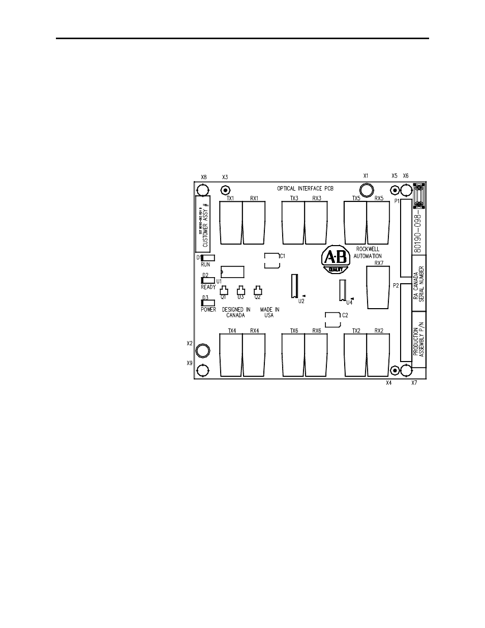
The Fiber Optic Interface (FOI) Boards are the interface between the
Drive Control Boards and the Gate Driver circuitry. The drive
control decides which device to fire, and sends an electrical signal to
the FOI boards. The FOI board converts that electrical signal to an
optical signal, which is transmitted via fiber optics to the gate driver
cards. Typically, the Transmit ports are Black and the Receive ports
are Blue. The gate driver accepts that signal and turns the device on
and off accordingly. The diagnostic fiber optic signals work the
same way, but the source is the gate driver boards and the destination
is the drive control boards.
Figure 6.76 – Fiber Optic Interface Board
The FOI boards are mounted directly on the DCBs using two parallel
14-pin connectors for the electrical connection, and plastic clips to
provide the mechanical strength. Each FOI board can handle the
Firing and Diagnostic duplex fiber optic connector for 6 devices,
whether they are SCRs or SGCTs. Physically, on the Drive Control
Boards, there is provision for 18 devices for the inverter and the
rectifier. This is enough capacity to handle the highest rated drive
that we currently produce. The top FOI board on the DCB is for the
„A‟ devices, the middle FOI board on the DCB is for the „B‟ devices,
and the bottom FOI board on the DCB is for the „C‟ devices.