Sgct testing – Rockwell Automation 7000L PowerFlex Medium Voltage AC Drive (C Frame) - Classic Control User Manual
Page 236
Commissioning 4-31
7000 “C” Frame
7000L-UM300I-EN-P – Juen 2013
SGCT Testing
The following instructions outline the procedure to be taken when
verifying SGCT semiconductors and all snubber components.
Expected SGCT Snubber Circuit Resistance and Capacitance values
are listed in the table below.
Table 4.A – SGCT Snubber Circuit Resistance and Capacitance Values
Drive Rating
Sharing Resistance
Snubber Resistance
Snubber Capacitance
Inverter
3300 to 6600 V
80 kΩ
7.5 Ω
0.5 µf
AFE Rectifier
3300 to 6600 V
80 kΩ
6.0 Ω
0.5 µf
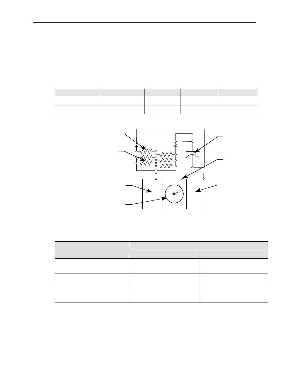
Sharing Resistor
Snubber Resistors
Qty. 4 or 5
Anode Chill Block
SGCT
Cathode Chill Block
Test Point
Snubber Capacitor
Sharing Resistor
Snubber Resistors
Qty. 4 or 5
Anode Chill Block
SGCT
Cathode Chill Block
Test Point
Snubber Capacitor
Figure 4.3 – SGCT Snubber Circuit Connections
SGCT Resistance Measurement
Measured Resistance
Inverter
Rectifier (PWM only)
SGCT Anode-Cathode Resistance
(Chill block to Chill block)
__________ – __________ kΩ
(Lowest)
(Highest)
__________ – __________ kΩ
(Lowest)
(Highest)
Snubber Resistance
(Test Point – Chill block above)
__________ – __________ Ω
(Lowest)
(Highest)
__________ – __________ Ω
(Lowest)
(Highest)
Snubber Capacitance
(Test Point – Chill block on Right)
__________ – __________ µF
(Lowest)
(Highest)
__________ – __________ µF
(Lowest)
(Highest)
If a device or snubber component is found to be damaged, it must be
replaced using the detailed procedures in Component Definition and
Maintenance.