Commissioning, Stop – Lenze EDS4900U-REG User Manual
Page 79
Commissioning
5-3
48XX/49XXSHB0399
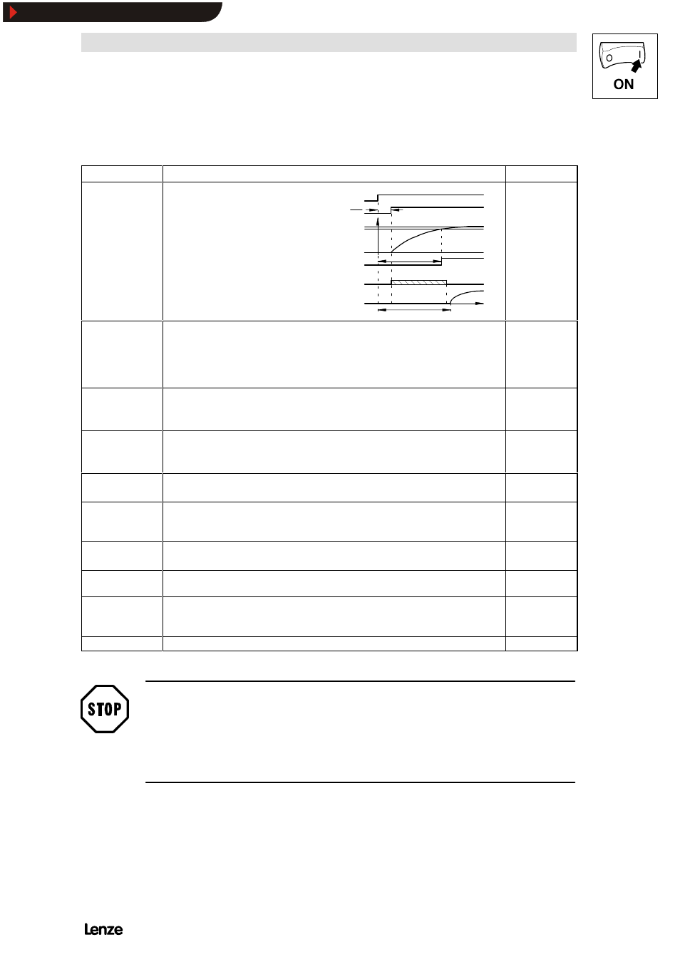
The following table describes briefly how to commission a DC shunt motor with an
attached tacho according to the example in FIG 5-1(see chapter 15).
Section
Activity
see also
Switch-on sequence 1.X2/28 (Ctrl. enable) must be opened (LOW)
2.Connect the mains
Approx. 0.5sec after mains connection the
controller is ready for operation.
The time t
1
depends on the initial response
of the field current
Typical values:
t
1
= 300ms ...600ms
t
2
= t
1
+ 20ms
FIG: Signal flow after mains connection
(see fig. on the right)
50 ms
TRIP
RDY
t
t
1
2
Mains on
Integration of the
armature controller
in its operating point
Controller
enable
field
I
90 % of the
rated current
Time
Armature
current
4900Str025
Input of the
motor data
3.Input of the motor nameplate data
- C083
Rated field current
- C084
Armature circuit time constant
- C088
Rated motor current
- C090
Rated motor voltage
Chapter 5.2
adaptation of tacho
4.Set S4 before adapting the tacho voltage
Chapter 7.1.2.2
p
constants
- C025
-2- Select adjustment of terminals 3, 4
- C029
Adjustment of actual speed
p
Set the current limit 5.Max. motor current
- C022
+ I
Amax
- C023
-I
Amax
Adjustment of max.
speed
6.Select the reference value for 100% setpoint
- C011
max. speed
Select direction of
rotation
7.CW rotation:
HIGH signal at X2/21 (+ 13...+ 30 V)
CCW rotation: HIGH signal at X2/22 (+ 13...+ 30 V)
Chapter 5.4
Setpoint selection
8.Apply a voltage higher than 0V (max. 10V)
- do not achivate JOG setpoint (LOW signal at X2/E4 and X2/E5)
Check whether LED
’RDY’ ison
9.If RDY is off and C067 is blinking, remove TRIP first.
Chapter 8.1 ff.
Controller enable
10. Assign HIGH-signal to X2/28 (+ 13...+ 30 V) and do not press STP
The motor will now run with the selected setpoint and in the selected direction of rotation. If
necessary, adapt the controller to your application.
Chapter 5.3
Additional settings
11. Further setting required for LECOM operation
Stop!
( Do not change the switch-off sequence
The controller must only be disconnected from the mains when it is inhibited or the
motor is in standstill (for mains switch-off logic see chapter 15.9.2).
Show/Hide Bookmarks