2 speed dependent armature current limitation, Monitoring, Change of the monitoring functions – Lenze EDS4900U-REG User Manual
Page 181: Configuration, Show/hide bookmarks
Configuration
7-90
48XX/49XXSHB0399
If the inputs are not assigned, constant values can be assigned via the input
codes. These values can also be stored in EEPROM via C003.
2. Function
The additional torque set-values have a summing influence on the n controller
output. The sum of these signals is limited to
100%.
Code
Name
Possible settings
Code
Name
Lenze Selection
Info
C148
Additional
torque
value 1
0
-100.0 % M
max
{0.1 %}
+ 100.0 % M
max
-200 % M
max
{1%}
+ 200 % M
max
Display only with terminal control. If the
terminal control is deactivated, the actual
terminal value will be accepted for
operation. In the armature setting range:
100 % M
max
correspond to 100 % I
max
(C022, C023)
C149
Additional
torque
value 2
0
-100.0 % M
max
{0.1 %}
+ 100.0 % M
max
-200 % M
max
{1%}
+ 200 % M
max
Display only with terminal control. If the
terminal control is deactivated, the actual
terminal value will be accepted for
operation. In the armature setting range:
100 % M
max
correspond to 100 % I
max
(C022/C023)
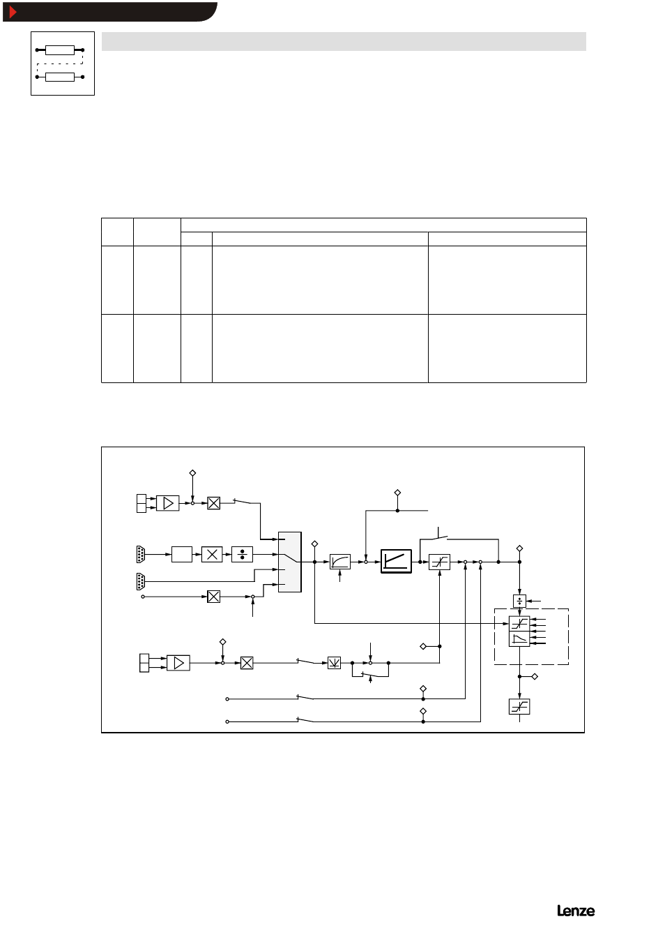
7.6.2
Speed dependent armature current limitation
4900Str078
-
+
2
1
C 0 4 7
C 0 5 0
+
C 0 5 1
4 0
4 2
4 3
4 1
+
C 1 4 5 / C 1 4 6
C 0 2 5 / C 0 2 7
3
4
± 1 8 0 V
C 2 7
C 2 8
C 2 5 / C 2 6
C 0 2 5 / C 0 2 7
-
A B
Q S P
C 0 7 0 V
C 0 7 1 T
C 0 7 2 K
p n
n n
d n
C 0 5 6
C 0 6 3
C 0 2 2 , C 0 2 3
C 3 1 0
C 3 1 1
C 3 1 2
C 3 1 3
C 3 1 4
C 0 2 5 / C 0 2 6
C 0 2 5 / C 0 2 6
C 0 2 5 / C 0 2 7
C 1 4 5 / C 1 4 6
+
+
C 1 4 8
C 1 4 9
C 1 4 6 / C 1 4 7
C 1 4 6 / C 1 4 7
+
-
1 0 0 %
C 2 8 2
C 1 9 8
n
s e t
a t n - c o n t r o l l e r
i n % o f n
m a x
n a c t
n
o f f s e t
T a c h o
I n c r e m e n t a l
e n c o d e r
R e s o l v e r
I
a c t
V
a r m a t u r e v o l t a g e
C 2 3 2
I · R - c o m p e n s a t i o n
0 V = n o t o r q u e
1 0 V = m a x . t o r q u e
E x t e r n a l t o r q u e l i m i t
C 0 0 5 C o n f i g u r a t i o n
n - c o n t r o l l e r
M
s e t
i n %
o f M
m a x
I
s e t
I
m a x
I
F a c t
A d d i t i o n a l t o r q u e s e t p o i n t 1
A d d i t i o n a l t o r q u e s e t p o i n t 2
s p e e d - d e p e n d e n t
c u r r e n t l i m i t a t i o n
E n c .
c o n s t .
FIG 7-51
Signal-flow chart (section) for speed-dependent armature current limitation
Purpose
If DC machines are drive with rated armature current in field weakening operation,
the segment voltage (at the armature) can reach impermissibly high values.
Show/Hide Bookmarks