Installation – Lenze EDS4900U-REG User Manual
Page 63
Installation
4-25
48XX/49XXSHB0399
Digital frequency output / encoder emulation
The output signal of the Sub-D socket X8 can be used for superimposed control
circuits to feed back actual values (synchronous running, digital frequency
coupling or positioning control). Depending on the configuration under C005, it is
assigned as a digital frequency output or as an output for the encoder emulation.
Features:
( Two 5V complementary signals (TTL signal), electrically shifted by 90°
( Current capacity 20mA per channel
( Current capacity at PIN 8 (+5V): max. 5mA
The output signal is internally derived from the resolver or incremental encoder
signal.
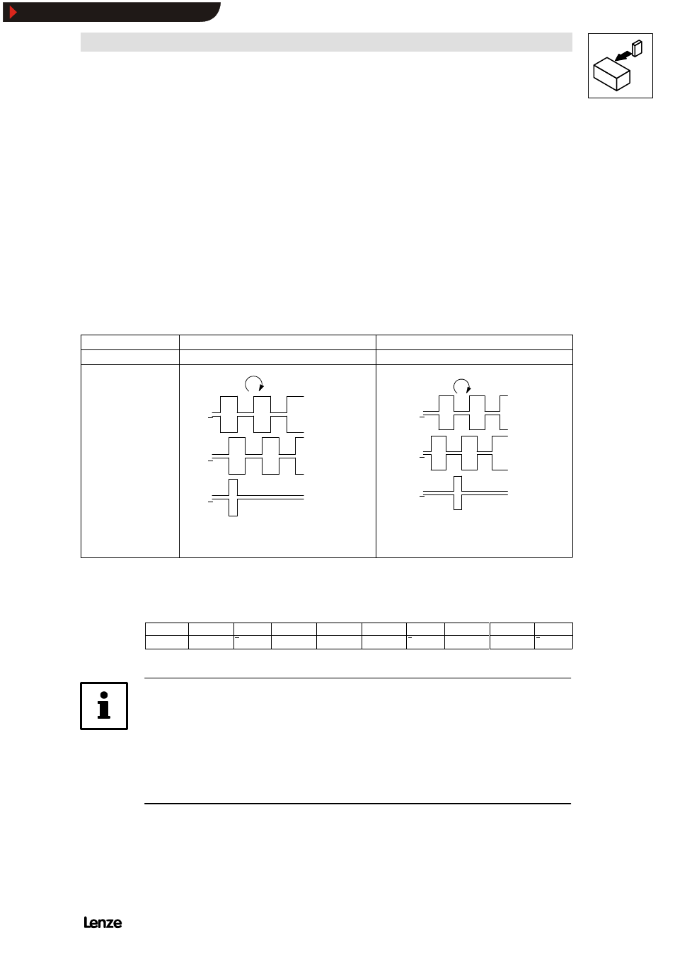
Resolver feedback
Incremental encoder feedback
Resolution
2048 increments per revolution
Constant of the incremental encoder
Signal type
A
A
B
B
Z
Z
4900Str019
A
A
B
B
Z
Z
4900Str020
FIG 4-19
Signal of digital frequency or encoder output X8 assignment of plug X8
Pin assignment of socket X8:
Pin
1
2
3
4
5
6
7
8
9
Signal
B
A
A
NC
GND
Z
Z
+ 5V
B
Note!
If fault messages occur at the encoder monitoring during resolver feedback to
superimposed systems:
( Exchange tracks A and B
( Use inverse tracks
Show/Hide Bookmarks