Motor potentiometer (s&h), Configuration, Show/hide bookmarks – Lenze EDS4900U-REG User Manual
Page 159
Configuration
7-68
48XX/49XXSHB0399
4900Str054
V p
V p
V p ( C 2 2 2 )
V p 2 ( C 3 2 5 )
V p ( C 2 2 2 )
V p 2 ( C 3 2 5 )
V p 3 ( C 3 2 6 )
C 2 2 2
1
0
C 2 2 3
n
C 2 2 4
v
T
T
p
V
-
C 3 3 2 T
C 3 3 3 T
i r
i f
C 3 3 4 T
C 3 3 5 T
i r
i f
C h a n g e o v e r
t o a d a p t a t i o n
C 3 2 9
C 1 4 5 / C 1 4 6
C h a n g e o v e r f o r
e x t e r n a l V p i n p u t
s e t 2
C 3 2 7
s e t 1
C 3 2 8
R F G
E v a l u a t i o n
- 1 0 0 % . . . + 1 0 0 %
P r o c e s s c o n t r o l l e r
c a n b e s w i t c h e d -
o f f e x t e r n a l l y
v i a F D I
I - c o m p o n e n t
c a n b e
s w i t c h e d - o f f
e x t e r n a l l y v i a
F D I
R F G
S u p p r e s s i o n
v i a F D I
T e r m . 1 , 2
T e r m . 3 , 4
T e r m . 6
T e r m . 8
M o t o r p o t . o u t p u t
A r i t h m e t i c b l o c k o u t p u t
D i g . f r e q u e n c y o u t p u t
C 3 3 0
T e r m . 1 , 2
T e r m . 3 , 4
T e r m . 6
T e r m . 8
M o t o r p o t . o u t p u t
A r i t h m e t i c b l o c k o u t p u t
D i g . f r e q u e n c y o u t p u t
P r o c e s s c o n t r o l l e r s e t p o i n t
E x t e r n a l V p s e t t i n g
T e r m . 1 , 2
T e r m . 3 , 4
T e r m . 6
T e r m . 8
M o t o r p o t . o u t p u t
A r i t h m e t i c b l o c k o u t p u t
D i g . f r e q u e n c y o u t p u t
A c t . p r o c e s s c o n t r o l l e r v a l u e
C 3 3 1
T e r m . 1 , 2
T e r m . 3 , 4
T e r m . 6
T e r m . 8
M o t o r p o t . o u t p u t
A r i t h m e t i c b l o c k o u t p u t
D i g . f r e q u e n c y o u t p u t
E v a l u a t i o n - 1 0 0 . 0 . . . + 1 0 0 . 0 %
M o n i t o r o u t p u t s
C 0 4 6
C 0 4 7
C 0 4 9
F i e l d c u r r e n t s e t p o i n t
A r i t h m e t i c b l o c k s
A / D c o n v . C 2 7 0 , C 2 7 1
P r o c e s s c o n t r o l l e r o u t p u t
± 1 6 3 8 4
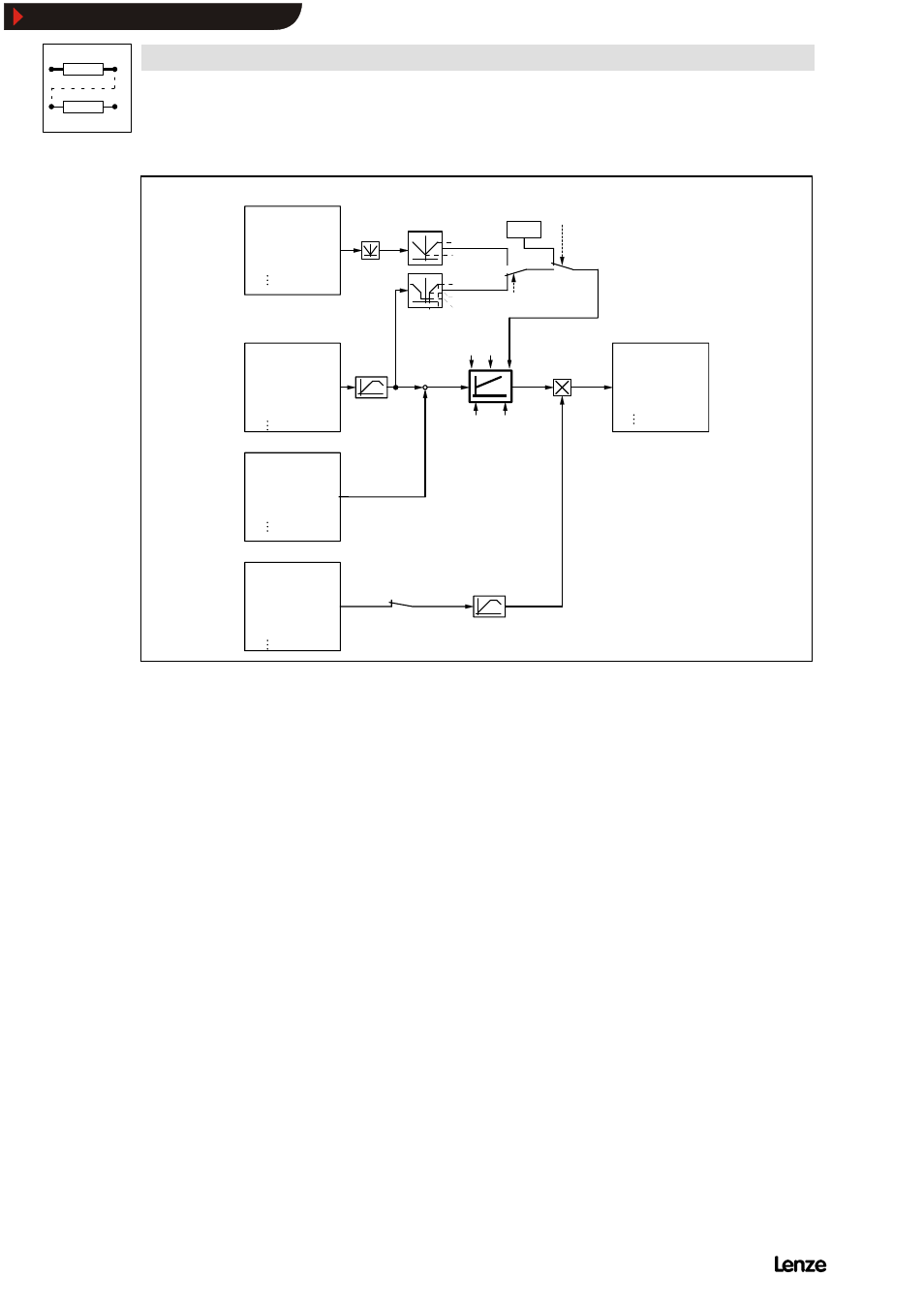
FIG 7-27
General signal structure of the process controller
Process controller inputs
1. Analog inputs
With the function ”freely assignable analog inputs” (C145...C147) the process
controller inputs ”set”, ”act.” and ”evaluation” can be assigned to other signal
sources (see table C145).
The inputs ”set” and ”evaluation” have their own codes (C330 and C331) and can
be parmaterised via keypad or interface. The setting via these codes is however
only possible if these no signal inputs are assigned to these codes.
The inputs ”set” and ”act.” represent the set-value and the actual value of the PID
controller.They are adjustable up to
á100%.
With the input ”evaluation”, the controller output can be weakened or inverted.
Values up to
á100% are adjustable. With the evaluation 100%, all process
controller influence is effective.
The inputs ”set” and ”evaluation” are connected to their own ramp function
generator before being processed any further. Acceleration and deceleration times
can be set separately (C332 to C335).
Show/Hide Bookmarks