10 dead-band element, Configuration – Lenze EDS4900U-REG User Manual
Page 175
Configuration
7-84
48XX/49XXSHB0399
7.5.10
Dead-band element
Purpose
The dead-band element is used to set interferences around the zero point (e.g.
interference on analog input voltages) to digital zero.
Parameter setting
4900Str070
C 1 4 6 / C 1 4 7
C 1 4 5 / C 1 4 6
C 6 2 2
C 1 4 5 / C 1 4 6
± 2 0 0 %
C 6 2 0
C 6 2 1
I n p u t
O u t p u t 1
O u t p u t 2
FIG 7-43
Dead-band element
1. Input
With the function ”freely assignable analog inputs” each input can be assigned to
a ”terminal signal” from the table in C145.
2. Outputs
With the function ”freely assignable analog inputs” the outputs can be assigned to
the targets listed under C146.
The output signal is limited to max.
200%.
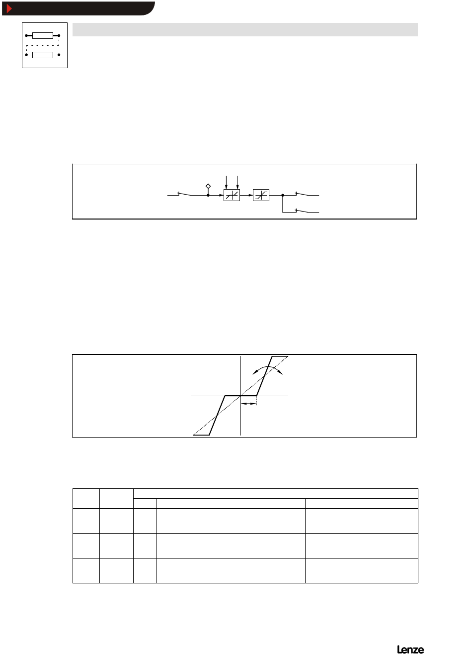
3. Function
4900Str071
C 6 2 1
C 6 2 0
I n p u t
O u t p u t
FIG 7-44
Characteristic for the dead-band element
Code C621 determines the dead band. The gain is set under code C620. The
function is symmetrical to the zero position.
Code
Name
Possible settings
Code
Name
Lenze Selection
Info
C620*
Gain dead
band
element
1.00
-10.00
{0.01}
+ 10.00
C621*
Dead band,
dead band
element
1.0 % 0.0 %
{0.1 %}
100.0 %
C622*
Input, dead
band
element
0%
-100.0 %
{0.1 %}
100.0 %
-200 %
{1 %}
+ 200 %
Display parameter only
Show/Hide Bookmarks